Reception method and apparatus

Active Publication Date: 2007-08-28
GOOGLE TECH HLDG LLC
View PDF4 Cites 15 Cited by
  • Summary
  • Abstract
  • Description
  • Claims
  • Application Information

AI Technical Summary

Problems solved by technology

Because of the increase in demand for data communications services, such as Internet services like access to the World Wide Web, the size of data messages and their frequency of transmission have increased and take longer to transfer on existing communication systems.
Unfortunately, when a mobile station, such as a cellular telephone handset, receives, for example, a wide-band time division multiple access (TDMA) transmission on a 100 KHz system, the mobile station is presently required to receive and decode the entire 100 KHz bandwidth of the wideband frequency domain channel to obtain and decode the desired data, regardless of whether the specific assignment for that mobile

Method used


Image

  • Reception method and apparatus
  • Reception method and apparatus
  • Reception method and apparatus

Examples


Embodiment Construction

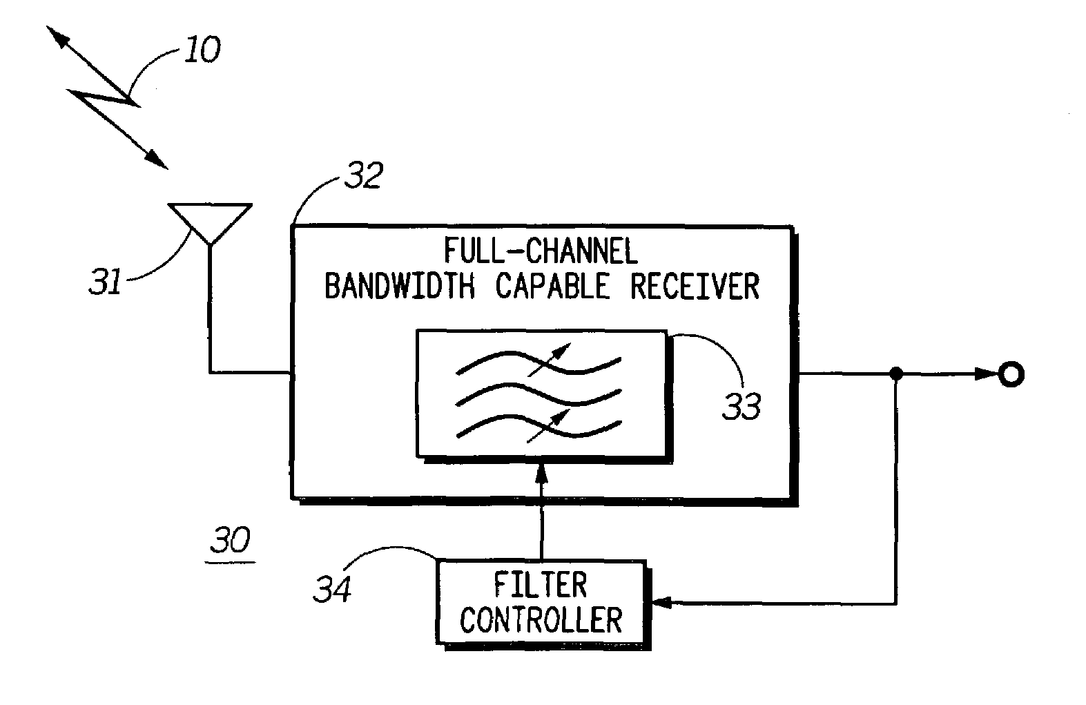
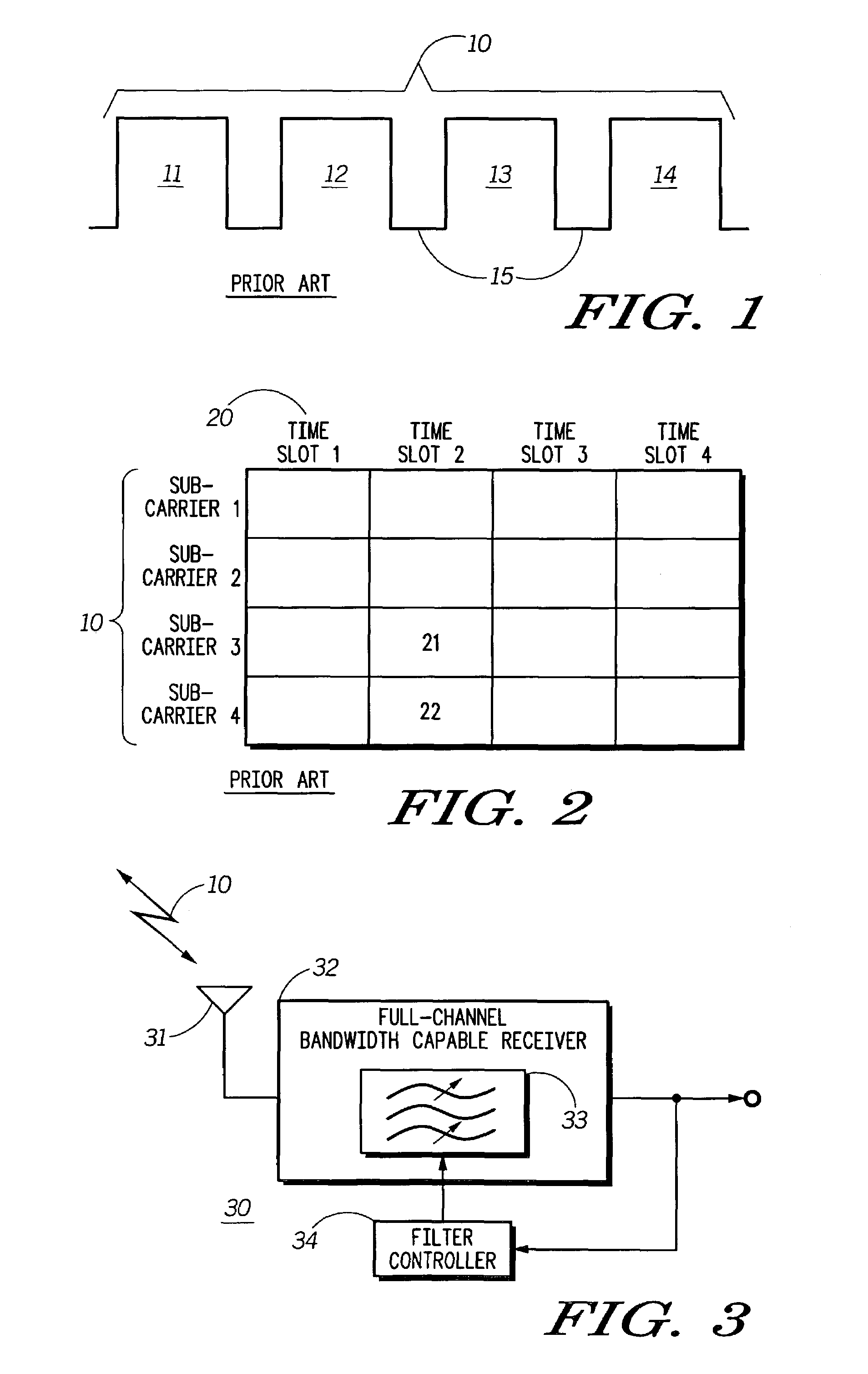
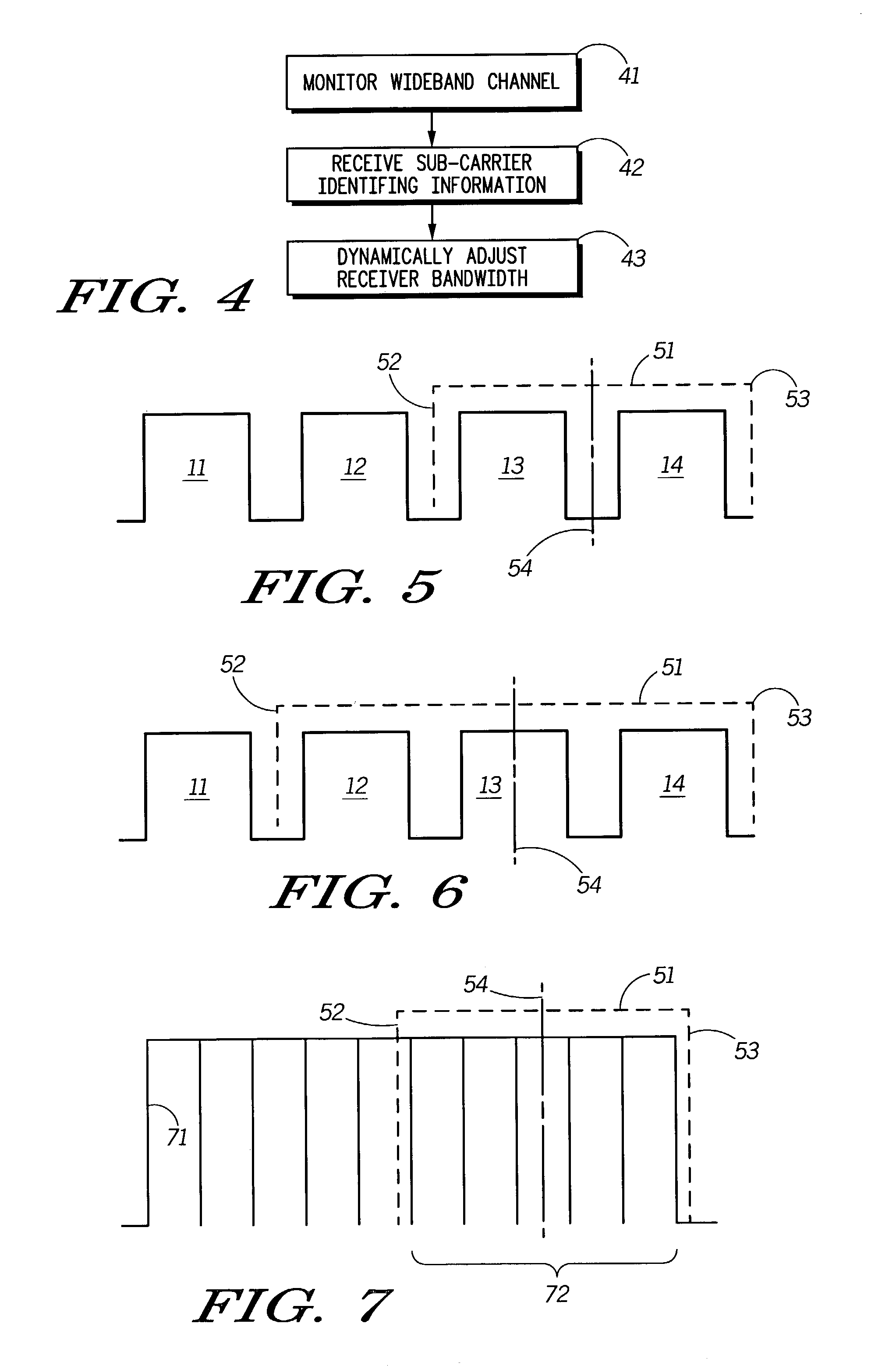
[0015]Pursuant to these various embodiments, at least a portion of a wideband frequency domain channel (comprised in a preferred embodiment of a plurality of sub-carriers) is monitored for reception of control information that identifies at least one specific sub-carrier. This specific sub-carrier (or sub-carriers) is then subsequently used by the mobile station to receive data (such as, for example, a user payload). Pursuant to a preferred embodiment, receiver bandwidth for the mobile station is dynamically adjusted during operation as a function, at least in part, of this control information. In particular, the receiver bandwidth is adjusted to facilitate reception of the relevant data while excluding reception of at least some other portion of the wideband channel (such as, for example, another sub-carrier) that is not to carry the relevant data.

[0016]In a preferred embodiment, such dynamic alteration of the receiver bandwidth can involve modification of the corresponding receive...


PUM


Abstract

Receiver bandwidth is dynamically altered during operation (with respect to, for example, filter bandwidth and/or filter center frequency) as a function, at least in part, of communication resource allocation.

Description

FIELD OF THE INVENTION[0001]The present invention relates generally to receiver performance.BACKGROUND OF THE INVENTION[0002]Communication systems are well known and comprise many types including land mobile radio, cellular radiotelephone, and personal communication systems to name a few. Within a communication system, transmissions are conducted between a transmitting device and a receiving device over a communication resource, commonly referred to as a communication channel. To date, the transmissions have typically consisted of voice signals. More recently, however, there has been rapidly growing interest in carrying other forms of signals, including high-speed packetized data signals that are suitable for video, audio, and other high bandwidth data applications.[0003]Because of the increase in demand for data communications services, such as Internet services like access to the World Wide Web, the size of data messages and their frequency of transmission have increased and take ...

Claims


Application Information

Patent Timeline
IPC IPC(8): H04Q7/20H04B1/10
CPCH04B1/1036
Inventor RUDOWICZ, MICHAELWIECZOREK, ALFRED
Owner GOOGLE TECH HLDG LLC
Why Eureka
Try Eureka