Pipe cleaner

a technology of pipe cleaners and cleaners, applied in the direction of cleaning hollow objects, cleaning equipment, mechanical equipment, etc., can solve the problems of unsound and porous joints, damage to wires used in electrical installations, and injuring workers

Inactive Publication Date: 2007-09-04
WALSH RICHARD T +1
View PDF17 Cites 15 Cited by
  • Summary
  • Abstract
  • Description
  • Claims
  • Application Information

AI Technical Summary

Benefits of technology

[0010]It has now been found that certain of the foregoing and related objects of the invention are attained by the provision of a tool for simultaneously cleaning inside and outside surfaces surrounding an open end portion of a pipe, which tool comprises a mounting head having at least one cleaning arm and at least one pipe-supporting arm, the latter being constructed to supportingly engage, from the outside, an end portion of a pipe. The cleaning arm has inner and outer support portions, which extend forwardly with respect to the mounting head and have confronting faces thereon that are spaced transversely from one another and define a rearwardly extending, forwardly open slot therebetween; each confronting face carries a pipe-cleaning element, which will usually be removably attached. Means is provided on the mounting head for mounting the cleaning arm and the pipe-supporting arm so as to extend forwardly, with respect to the head, in transversely spaced relationship to one another and in position to enable receipt, within the slot between the forwardly extending support portions of the cleaning arm, of the wall defining the open end portion of a pipe that is engaged and supported by the supporting arm; the means for mounting enables adjustment of the transverse spacing between the cleaning arm and the pipe-supporting arm. Relative rotation of the mounting head and a pipe that is so engaged, supported and received, about the axis of the pipe end portion, will cause the pipe-cleaning elements to effect cleaning simultaneously of the surrounding inside and outside pipe surfaces.
[0011]The means for mounting will, more particularly, usually comprise a rectilinear positioning screw that is mounted transversely in the mounting head for rotation about its axis. Either the cleaning arm or the pipe-supporting arm (and normally both) is formed with a threaded transverse passage though which the positioning screw extends, which passage engages a correspondingly threaded section of the positioning screw. As long as one of the arms is effectively fixed, or both arms are threadably engaged as hereinafter described, rotation of the positioning screw will effect adjustment of the transverse spacing between the cleaning arm and the pipe-supporting arm so as to accommodate pipes throughout a range of diameters.
[0014]At least the inner support portion of the cleaning arm will advantageously have a widest dimension that is not in excess of about one-half inch, so as to facilitate insertion into pipes of small diameter (e.g., pipes having an inside diameter of one inch or less) and minimize interference with relative rotation. Means will desirably be provided for biasing the pipe-cleaning element on the inner support portion of the cleaning arm toward the outer support portion, so as to promote intimate contact and better accommodate surface and structural irregulations or variations in the pipe (e.g., out-of-roundness), and a small metal file strip or fillet, or other element that is effective for abrading the end of a pipe, may advantageously be disposed on a support surface at the rearward end of the slot in the cleaning arm.

Problems solved by technology

Surfaces that are sharp, rough, contaminated or oxidized can inhibit soldering, brazing, and bonding, resulting in joints that are unsound and porous; slivers of material, burrs and sharp edges can also injure workers and can damage wire used in constructing an electrical installation.

Method used


Image

  • Pipe cleaner
  • Pipe cleaner
  • Pipe cleaner

Examples


Embodiment Construction

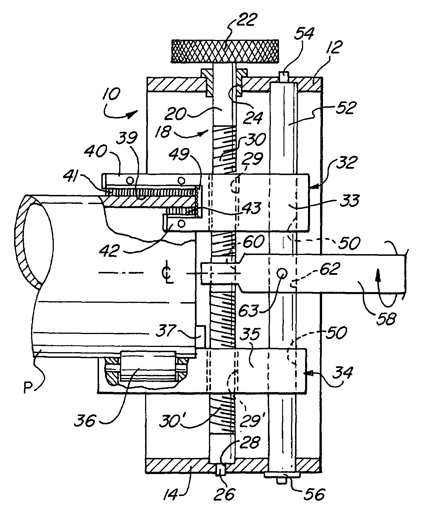
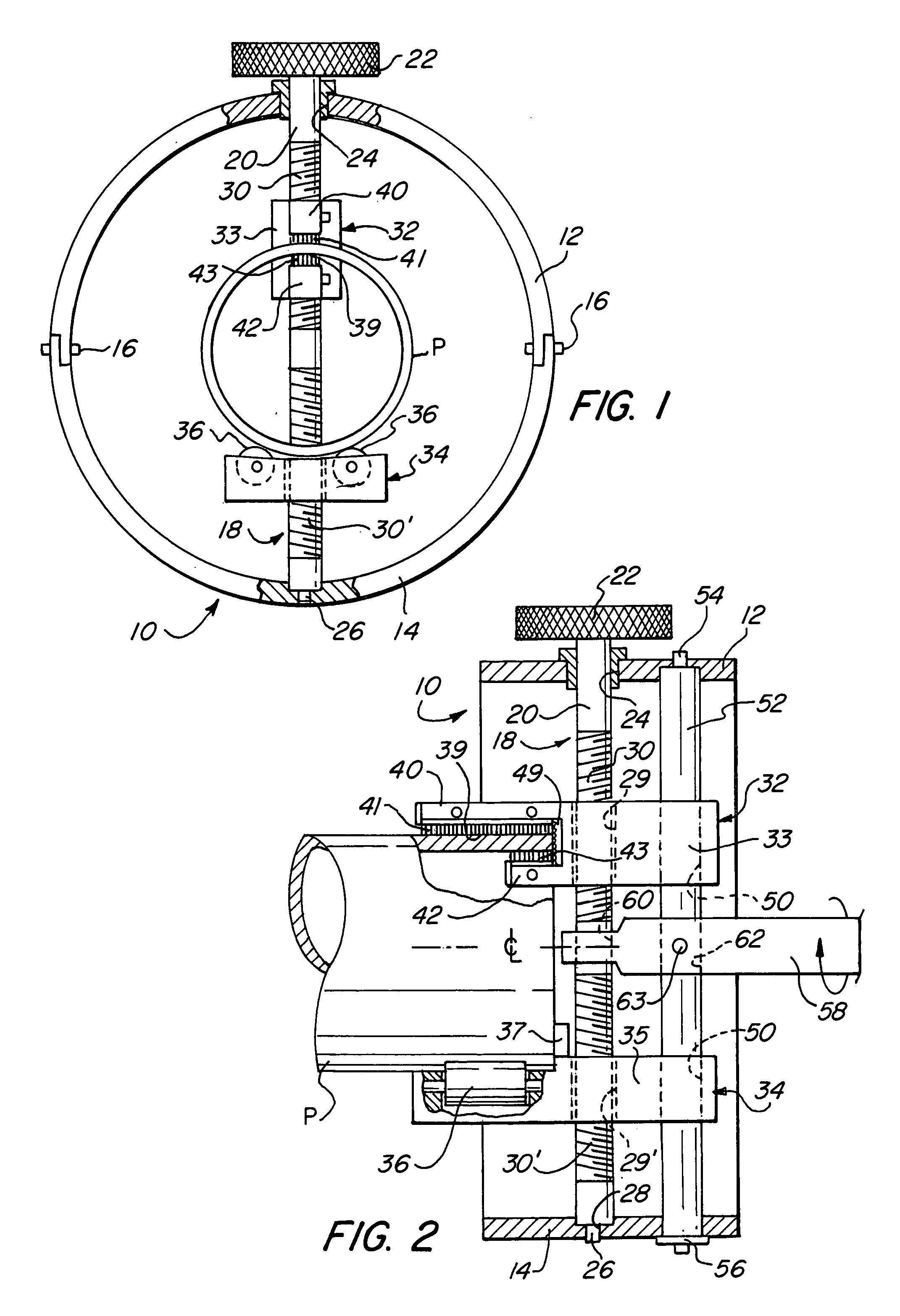
[0021]Turning initially to FIG. 1 of the drawings, therein illustrated is a cleaning tool embodying the present invention and consisting of a head, generally designated by the numeral 10, comprised of two semi-circular collar sections 12, 14 which are interengaged and joined to one another by fasteners 16 to thereby form a full circular collar. A rectilinear positioning screw has a shaft, generally designated by the numeral 18, which extends diametrically across the collar of the head 10, with a proximal plain portion 20, adjacent a knurled operating knob 22, passing through a round hole 24 in the collar section 12 and with a distal small-diameter tip element 26 rotatably received in a mating socket 28 formed into the opposite collar section 14. The positioning screw has threaded portions, 30, 30′ intermediate its ends, the threads of which are directed oppositely to one another (i.e., a right-hand thread and a left-had thread).

[0022]The tool includes a cleaning arm, generally desig...


PUM


Abstract

A tool for simultaneously cleaning inside and outside surfaces surrounding an open end portion of a pipe includes a cleaning arm and a pipe-supporting arm mounted in a head for adjustment of the transverse spacing therebetween. Support portions on the cleaning arm have confronting faces spaced transversely from one another and defining a rearwardly extending, forwardly open slot adapted for the receipt of the wall of a pipe supported on the pipe-supporting arm, and a pipe-cleaning element is disposed on each of the confronting faces of the support portions. Relative rotation of the mounting head and a pipe so positioned will cause the cleaning elements to effect simultaneous cleaning of the surrounding inside and outside surfaces of the pipe end portion.

Description

BACKGROUND OF THE INVENTION[0001]It is well known in the art that, during installation, end portions of pipes, tubing, and like conduits, such as are usually made of copper, aluminum or plastic and are used for the containment of electrical wires or for carrying water, heating or cooling gases, and other fluids, must be cleaned on the inside and outside so as to facilitate the introduction of wires and to ensure sound assembly with fittings, couplings, and the like. Surfaces that are sharp, rough, contaminated or oxidized can inhibit soldering, brazing, and bonding, resulting in joints that are unsound and porous; slivers of material, burrs and sharp edges can also injure workers and can damage wire used in constructing an electrical installation.[0002]A pipe cleaning system that is capable of simultaneously cleaning the interior and exterior of the open end portion of a copper pipe is disclosed in Knowles U.S. Pat. Nos. 6,704,964 and 6,745,426. Additional United States patents of i...

Claims


Application Information

Patent Timeline
Patent Type & Authority Patents(United States)
IPC IPC(8): B08B1/00
CPCB08B9/021
Inventor WALSH, RICHARD T.WALSH, JR., RICHARD T.
Owner WALSH RICHARD T
Why Eureka
Try Eureka