
Light projector

a projector and light technology, applied in the field of light projectors, can solve the problems of narrow light projector range, troublesome state, and need for plurality of light projectors, and achieve the effect of easy removal

Inactive Publication Date: 2007-09-04
LIGHT BOY
View PDF13 Cites 20 Cited by
  • Summary
  • Abstract
  • Description
  • Claims
  • Application Information

AI Technical Summary

Benefits of technology

[0006]In accordance with the light projector of this invention constituted as described above, when the lighting instrument is lit, the light is changed into a soft-feeling light through the balloon so as to enable the light to be projected in an outward entire circumferential direction, so that it is possible to radiate the light over a wide range without causing a driver to feel glare.
[0008]In such a construction as described above, the balloon is rigidly fixed to the main body, so that the bulged-out state of the balloon can be kept tightly.
[0010]In such a configuration as above, this invention provides a fixed structure in which an opposing portion in the balloon is held by the surfaces of the inner plate and the outer plate, so that there is no possibility that the balloon is broken or has a punctured hole at the fixed portion and the balloon can be held tightly.
[0016]In such a configuration as above, the barrel part of the balloon can be easily removed by operating the engagement means.

Problems solved by technology

However, when this is applied at a nighttime road construction work, there occurs a possibility that the projected light is too bright for a driver of running vehicle and in particular, this may cause a troublesome state at the work site such as a highway and the like.
In addition, the light radiated from the aforesaid lighting instrument is limited only in a forward direction as to the light projecting direction with a reflector, so that its light projecting range becomes narrow and it becomes a disadvantage that a plurality of light projectors are required in the case that the work area is wide.

Method used


Image

  • Light projector
  • Light projector
  • Light projector

Examples


Embodiment Construction

[0031]Referring now to the accompanying drawings, a preferred embodiment of this invention will be described.

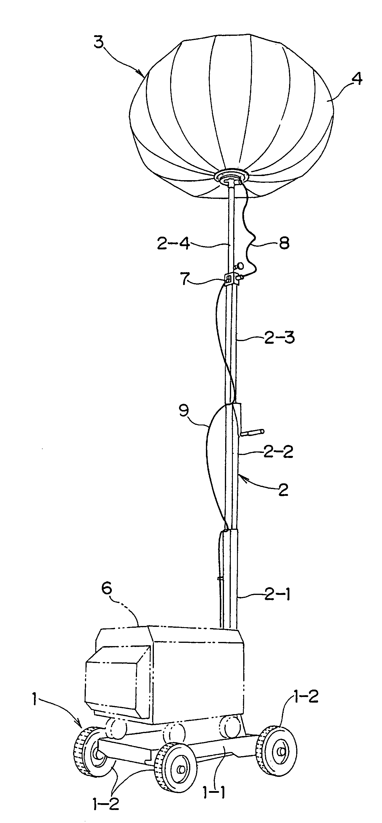
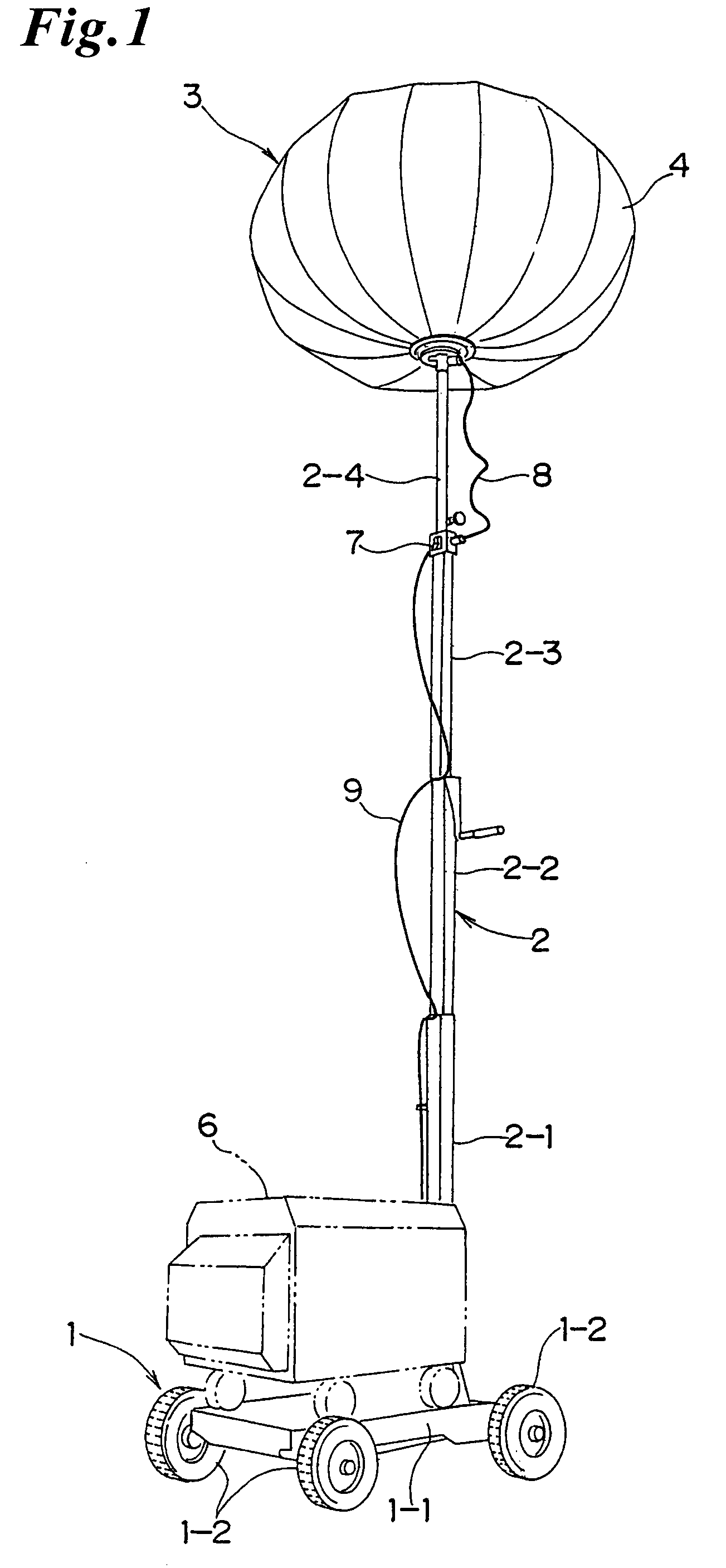
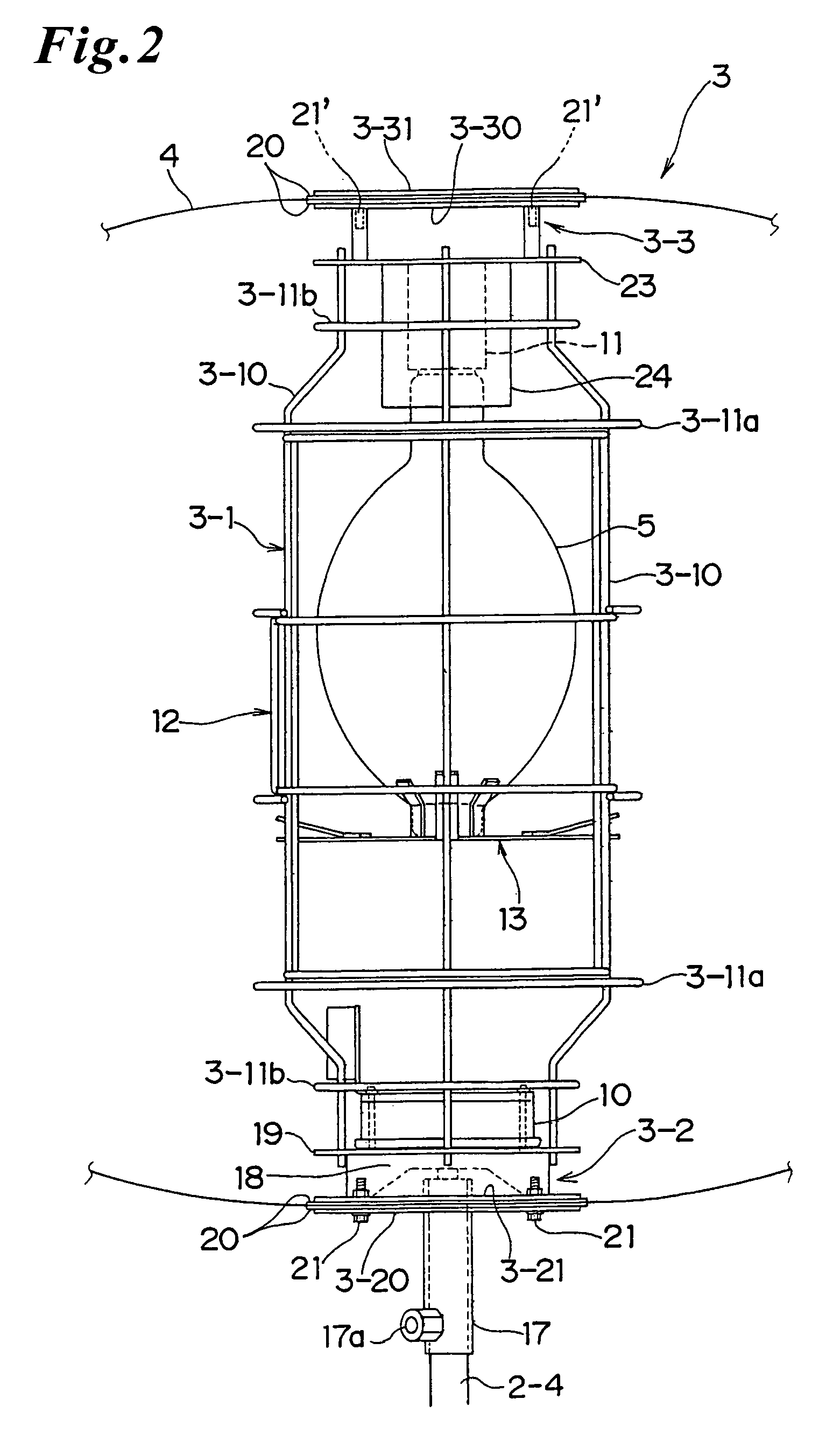
[0032]FIG. 1 is a perspective view for showing one preferred embodiment of a light projector of this invention. This light projector A is comprised of a power generator 6; a bogie 1 for mounting the power generator 6; an extendable or retractable supporting column 2 vertically installed at the bogie 1; a balloon 4 installed at the upper end of the extendable or retractable supporting column 2; and a lighting instrument 3 having at least an electric bulb 5 stored in this balloon 4. This light projector is configured such that the power generator 6 and the lighting instrument 3 can be electrically energized to cause the lighting instrument 3 to be lit through electrical supplying from the power generator 6, glaring light supplied from the electric bulb 5 is passed through the balloon 4 and changed into a soft light not showing any glaring state and the light can be projected in...


PUM


Abstract

A light projector includes a power generator 6; a bogie 1 for mounting the power generator 6; an extendable or retractable supporting column 2 vertically installed at the bogie 1; a balloon 4 arranged at an upper end of the extendable or retractable supporting column 2; and a lighting instrument 3 stored in the balloon 4, wherein the power generator 6 and the lighting instrument 3 can be electrically energized. The lighting instrument 3 is lit through supply of electricity from the power generator 6 installed at the bogie 1 and the light thus generated is changed into a soft-feeling light through the balloon 4 so as to enable the light to be projected in an outward entire circumferential direction of the balloon 4. Thus, even if the light projector is used as a night-time lighting for a road work and the like, the light of the lighting instrument can be radiated in a wide range without causing a driver of a passing vehicle to feel its glaring effect.

Description

TECHNICAL FIELD[0001]This invention relates to a light projector used as a nighttime lighting unit applied in a work site, a game ground and a camp or the like. More particularly, this invention relates to a light projector which can be effectively used as a nighttime lighting unit for a road construction or the like, for example, by radiating light from a light source indirectly and reducing a lighting glare.BACKGROUND ART[0002]It is well known in the prior art to provide a light projector in which a desired number of spot-light type lighting instruments for use in radiating light of a lamp (an electrical bulb) in a forward direction by a reflector are installed at an upper end of an extendable or retractable supporting column vertically installed at a bogie for use in mounting a power generator.[0003]In this type of light projector, it is of course apparent that the light (projected light) radiated from the aforesaid lighting instrument is bright to cause a worker at site to easil...

Claims


Application Information

Patent Timeline
Patent Type & Authority Patents(United States)
IPC IPC(8): F21V17/06F21S8/00F21S10/00F21V3/00F21V15/02F21V21/22F21Y101/00
CPCB60P3/18F21L14/04F21S9/04F21V3/023F21V11/04F21V11/16F21V11/18F21V17/164F21V19/007F21V21/0808F21V21/22F21V15/02F21V19/04F21V25/04F21W2131/1005F21S8/00
Inventor YOSHIMORI, NORIHITOKIRIYAMA, MAKOTO
Owner LIGHT BOY
Learn More