Recorded data deleting device for hard disk

a data eraser and hard disk technology, applied in the field of record erasers, can solve the problems of affecting the efficiency of data erase, and consuming a lot of time, and achieves the effects of reducing workload, efficient data erase, and reducing time consumption

Inactive Publication Date: 2007-09-04
ORIENT INSTR COMP CO LTD
View PDF12 Cites 5 Cited by
  • Summary
  • Abstract
  • Description
  • Claims
  • Application Information

AI Technical Summary

Benefits of technology

[0009]Further, the magnetic field produced in the coil is used effectively, so as to make the coil smaller and lighter in weight and thus making the entire eraser lighter in weight, compared with a conventional arrangement of the hard disk drive at the outer side of the coil.
[0011]In addition to the first advantage, the permanent magnet is provided in a position where the magnet exerts a magnetic force on the hard disk drive inserted in the cavity of the eraser, thereby ensuring further lightness in its weight. Further, the magnetic field produced in the cavity is set within the range of 6,000 to 15,000 gauss at the magnetic flux density, thereby making sure to erase data. Still further, since the DC power supply circuit includes a capacitor for charging and discharging and a switching device for discharging the capacitor into the coil, the discharge of the capacitor into the coil by the switching device produces the magnetic field in the coil. Yet further, production of the magnetic field in the coil by the discharge of the capacitor is set for duration of 10 ms or less, thereby enabling an efficient data erase in a short period.

Problems solved by technology

However, the erasing process by the data overwriting has a problem of heavy workloads and time-consuming.
For example, it takes more than 12 hours to erase data on a hard disk of 20 gigabytes of storage capacity.
However, in the case of erasing data in a hard disk drive by using the eraser, since a hard disk inside the hard disk drive is accommodated within a casing made of metal such as iron and aluminum, the magnetic force does not reach the hard disk inside the hard disk drive, failing to erase data recorded on the hard disk only with the hard disk drive arranged at an outer face of the eraser and with a magnetic field generated by the eraser.
To generate a stronger magnetic field, there is a problem to make a coil heavier, resulting in increasing a weight of the entire eraser.

Method used


Image

  • Recorded data deleting device for hard disk
  • Recorded data deleting device for hard disk
  • Recorded data deleting device for hard disk

Examples


Embodiment Construction

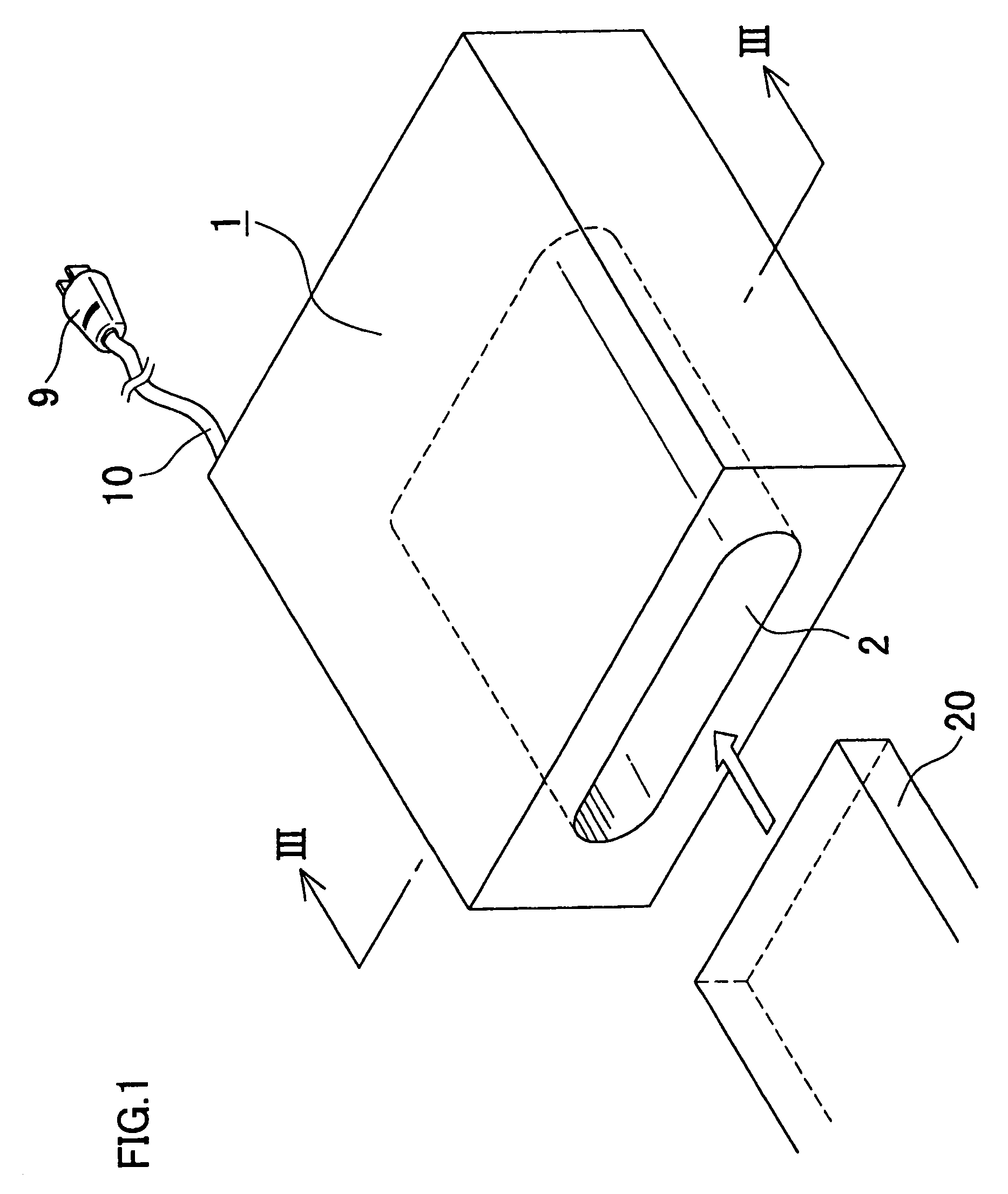
[0017]FIGS. 1 to 4 show a data eraser for a hard disk drive that is a preferred embodiment of the present invention.

[0018]Referring to the figures, a reference numeral 1 denotes the data eraser that includes a cavity 2 for insertion of a hard disk drive, with an opening at one end face of the eraser, in an oval (a racetrack) shape at cross section, and extending horizontally.

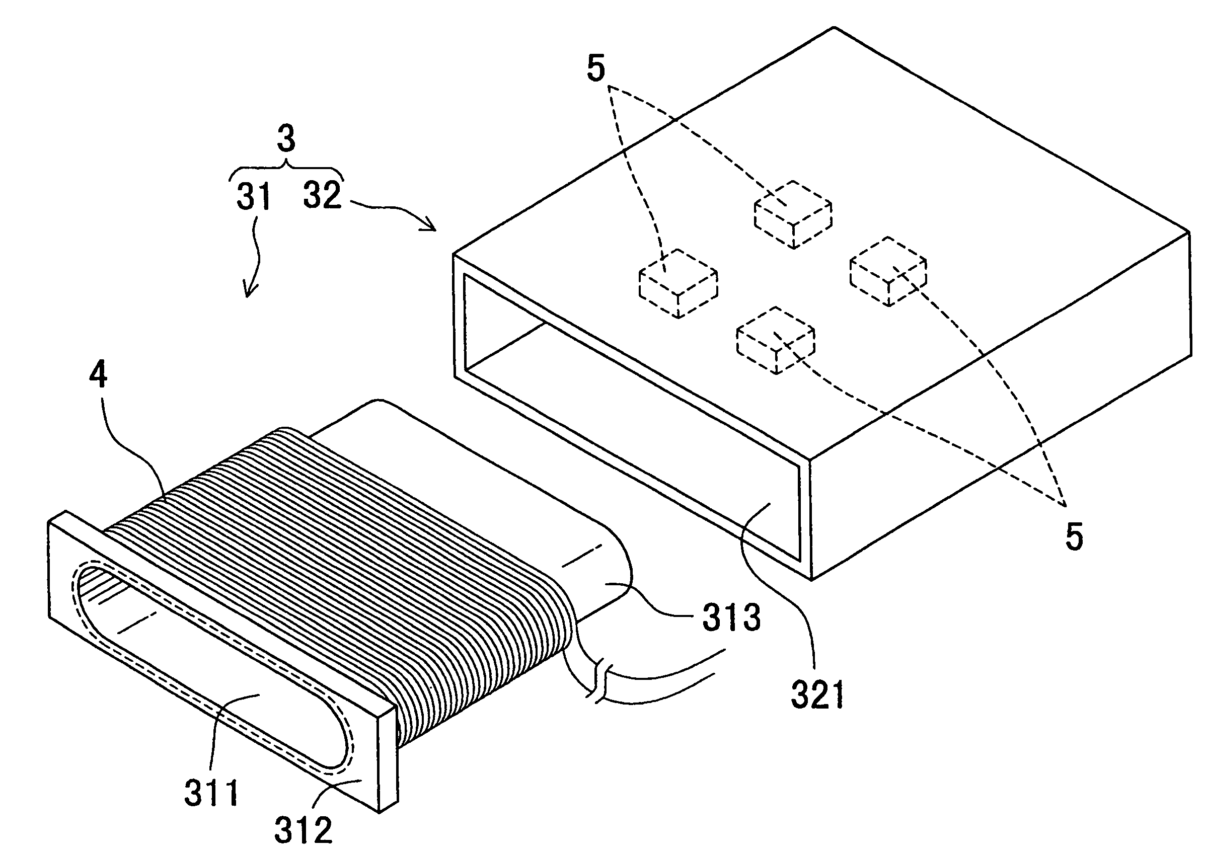
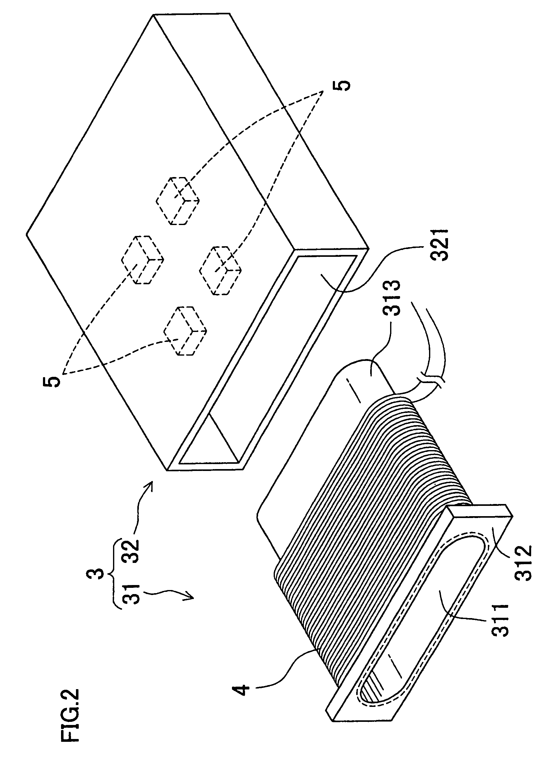
[0019]A casing assembly 3 of a box shape for arranging a coil shown in FIG. 2 is incorporated in the eraser 1. The casing assembly 3 consists essentially of a first casing component 31 made of plastic and a second casing component 32 also made of plastic. The first casing component 31 includes a rectangular flange 312 having an opening 311 of an oval (a racetrack) shape and a coil holder 313 of a tubular shape extending backward of the flange 312 from the edge of the opening 311 of the flange 312. The opening 311 and the internal space of the coil holder 312 form the cavity 2 for insertion of the hard disk drive...


PUM

PropertyMeasurementUnit
magnetic flux densityaaaaaaaaaa
weightaaaaaaaaaa

Abstract

A recorded data eraser 1 defines therein a cavity 2 for insertion of a hard disk drive 20 in the cavity 2 and includes a coil 4 being arranged around the cavity 2 so as to encircle the hard disk drive 20 when the hard disk drive 20 is inserted in the cavity 2, and a DC power supply circuit 8 for producing a magnetic field in the coil 4.

Description

TECHNICAL FIELD[0001]The present invention relates to a recorded data eraser for a hard disk drive used for erasing data recorded in a hard disk drive.BACKGROUND ART[0002]When a hard disk drive is abandoned or reused, data recorded on a hard disk as a recording medium in the hard disk drive are commonly erased in view of confidential nature.[0003]Such erase of recorded data in a hard disk drive is conventionally done by repeatedly writing predetermined data such as “00” over data on the hard disk. However, the erasing process by the data overwriting has a problem of heavy workloads and time-consuming. For example, it takes more than 12 hours to erase data on a hard disk of 20 gigabytes of storage capacity.[0004]On the other hand, as an eraser for erasing data on floppy disks and tapes, which are also recording media, a toroidal coil formed by a conductive wire wound around an outer periphery of a ring-shaped core, arranged in a casing of an eraser body and connected to an AC power i...

Claims


Application Information

Patent Timeline
Patent Type & Authority Patents(United States)
IPC IPC(8): G11B5/03H01F13/00H01H47/00G11B5/012G11B5/024
CPCG11B5/012G11B5/0245H01F13/006
Inventor ITO, TOMOAKI
Owner ORIENT INSTR COMP CO LTD
Why Eureka
Try Eureka