Method of controlling an actuator, and disk apparatus using the same method

a technology of actuators and actuators, applied in the direction of instruments, data recording, and support for heads, can solve the problems of damage to the head and the surface of data area, damage to the data recording area, damage to the data recording area, etc., and achieve the effect of reducing the power consumption and downsizing of the apparatus, reducing the risk of actuators being released from the refuge place, and reducing the size of the apparatus

Inactive Publication Date: 2007-09-04
PANASONIC CORP
View PDF19 Cites 160 Cited by
  • Summary
  • Abstract
  • Description
  • Claims
  • Application Information

AI Technical Summary

Benefits of technology

[0050]This structure allows issuing a starter command to the disk apparatus, whose actuator is in the refugee place, to start working, and when the actuator starts loading, the tab can jump from the second plane of the refuge place and to leave the ramp block with a rather small amount of current thanks to the availability of repulsive force of the actuator and repulsive driving force of the voice coil motor. The actuator kept at the refuge place can be thus released with a smaller amount of current applied to the voice coil for the release.
[0056]The method discussed above allows the tab to jump from the plane of the refuge place for leaving the ramp block with only a small amount of current thanks to the availability of the repulsive force generated when the actuator moves towards the recording medium and the repulsive driving force of the voice coil motor. The amount of current to be applied to the voice coil for releasing the actuator from the refuge place can be thus reduced. As a result, power saving and downsizing of the apparatus can be achieved. The power supply can employ a lower voltage, and yet, higher reliability is achieved, so that an inexpensive actuator and a disk apparatus are obtainable.

Problems solved by technology

When the actuator receives an external shock during the rest of the disk apparatus at the predetermined place near the periphery of the disk, the actuator possibly moves from a refuge place to a data recording area on the medium, thereby damaging the surface of the data recording area due to a collision between the head and the surface of the medium.
Here is another possibility of damaging the data recording area; when the apparatus starts working with the head held at the predetermined parking zone above the medium, sliding of the head on the surface of the medium sometimes damages the head and the surface of data area.
On top of that, a collision between the actuator and other elements of the disk apparatus causes fatal damage to the other elements or the actuator.
However, when the leaf spring is fixed to the lower position or the upper position, namely, the actuator is in the lock released status or in the locked status, the current is not supplied to the solenoid coil.
However, it has comparatively weak resistance to a large shock or a shock having vertical components with respect to the swing direction.
The holding device cannot function as a reliable holder when it receives a shock.
Since the holding device needs the iron chip and the permanent magnet for holding the actuator at the refuge place, the number of elements forming the apparatus increases, which boosts the cost of the apparatus.
As a result, a large size solenoid coil is required.
On top of that, a space is needed for placing respective elements forming the actuator latch device which locks the actuator at the refuge place, so that it becomes difficult to downsize the disk apparatus, or save an electric current, i.e. save power of the disk apparatus.
The actuator latch device needs a large number of elements, which boosts the cost of the apparatus, and at the same time, causes to lower the reliability.
However, the inertia latch device needs a large number of elements and also a space for accommodating those elements.
Those factors increase the cost of the device and resist downsizing the device.

Method used


Image

  • Method of controlling an actuator, and disk apparatus using the same method
  • Method of controlling an actuator, and disk apparatus using the same method
  • Method of controlling an actuator, and disk apparatus using the same method

Examples


embodiment 1

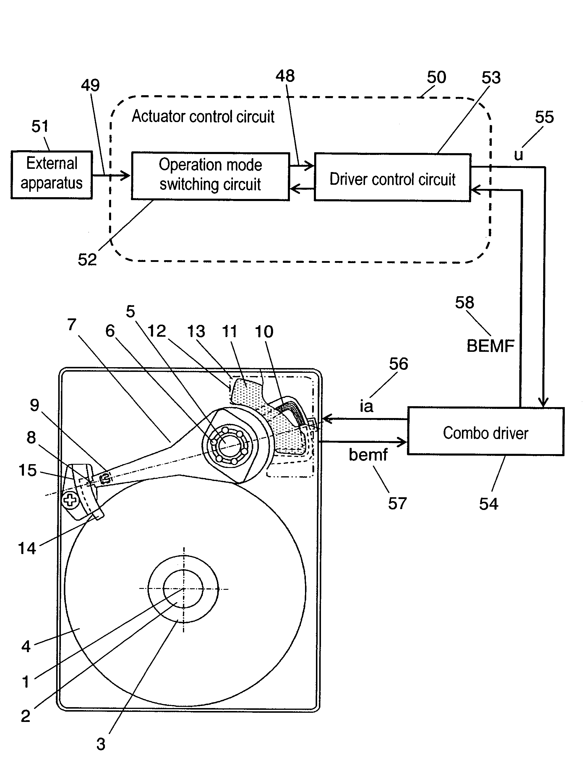
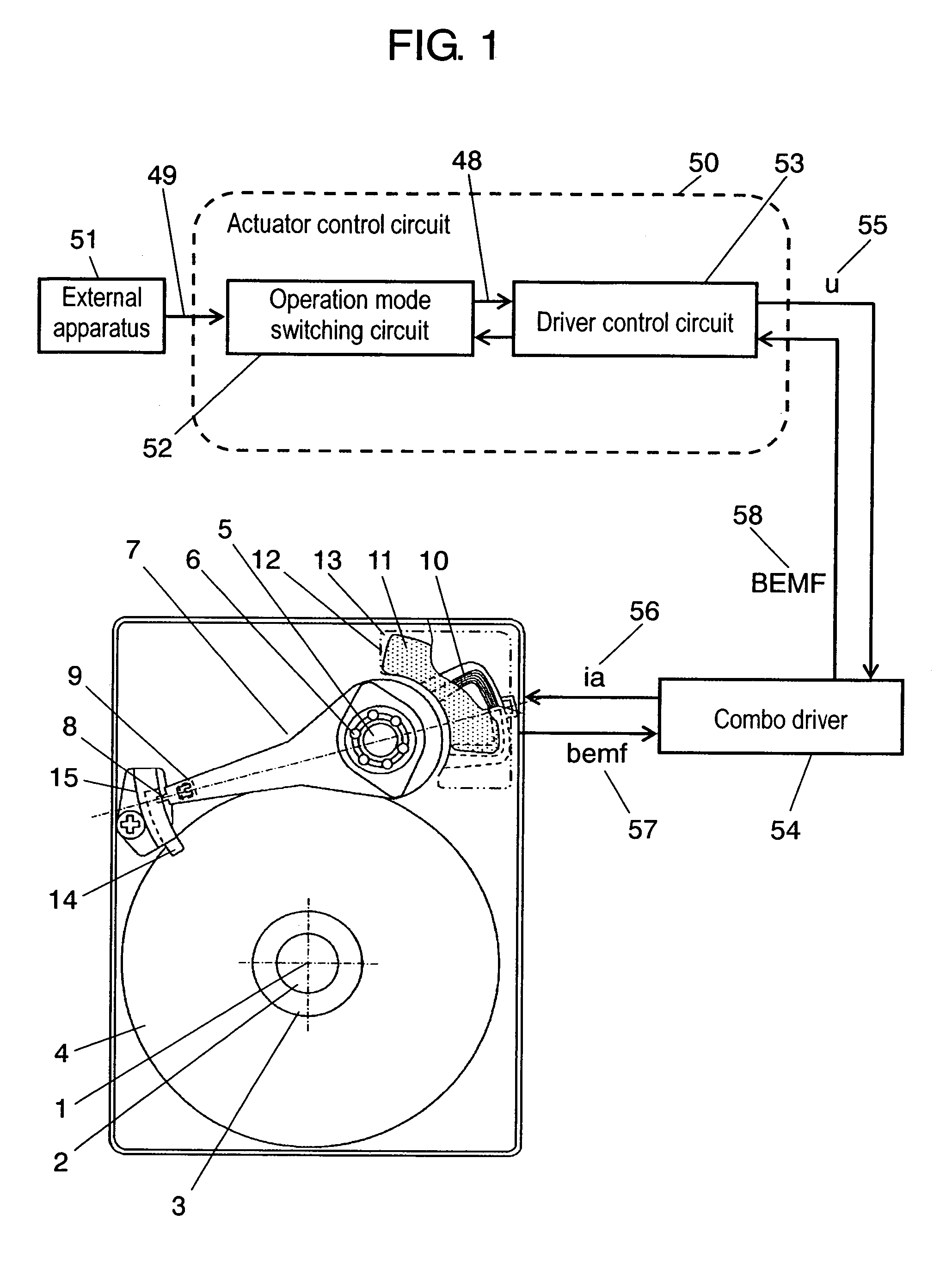
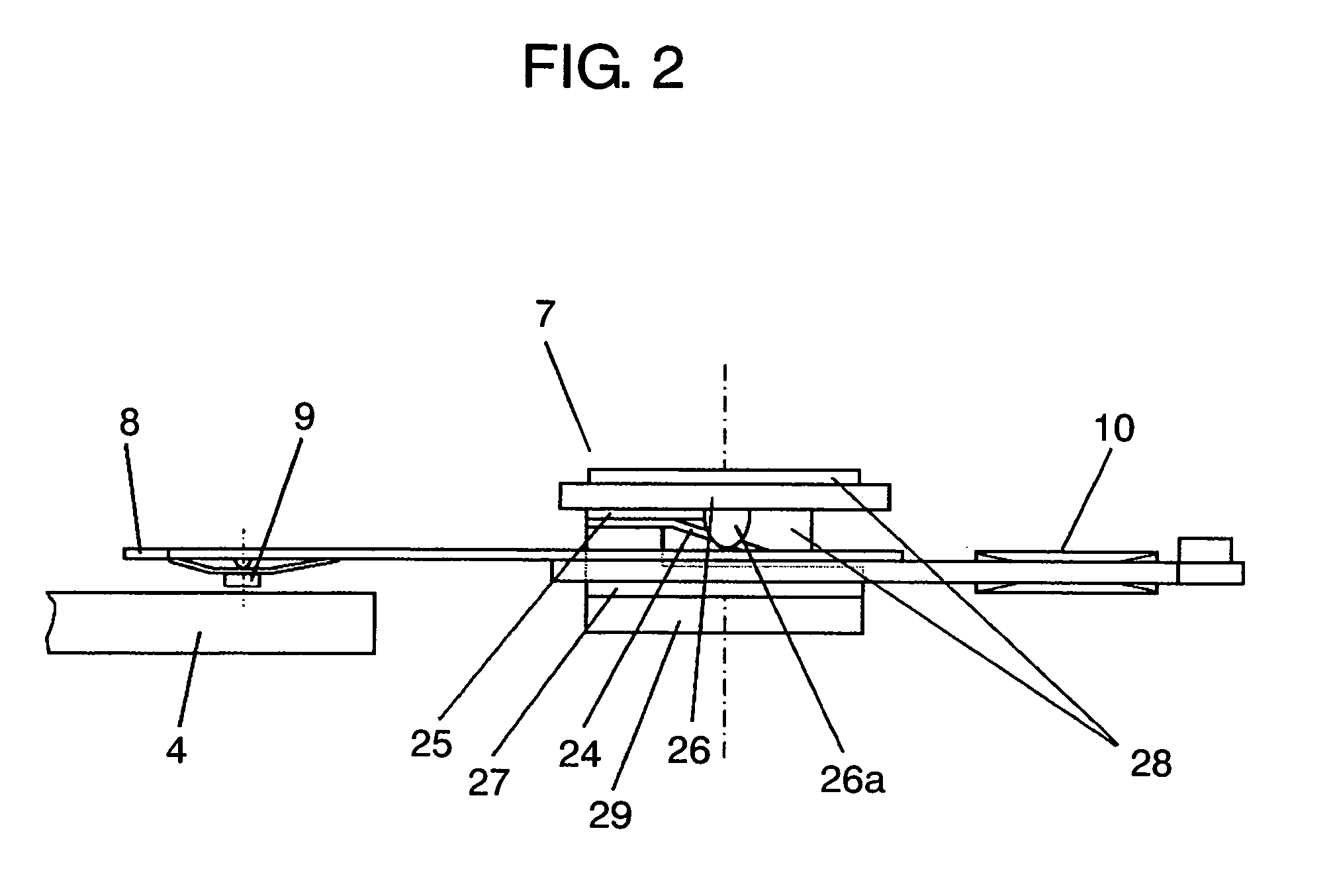
[0084]FIG. 1-FIG. 12 illustrate how to control an actuator and also show the magnetic disk apparatus in accordance with the first embodiment of the present invention. FIG. 1 shows a schematic diagram illustrating a main section of a magnetic disk apparatus when the actuator is at a refuge place. FIG. 2 shows a schematic lateral view illustrating a structure of the actuator. FIG. 3 shows a perspective exploded view illustrating the structure of the actuator. FIG. 4 shows a plan view illustrating a vicinity of a ramp block when the actuator is at the refuge place. FIG. 5 shows a sectional development of the ramp section, a tab and a recording medium cut along line B-B in FIG. 4 and developed. FIG. 6 shows an enlarged plan view illustrating a voice coil and a magnet viewed from the magnet side of a VCM. FIG. 7A shows a relation between a rotational position of the actuator and rotary torque of the VCM. FIG. 7B shows a relation between a rotational position of the actuator and repulsive...

embodiment 2

[0146]FIG. 13-FIG. 16 illustrate a method of controlling an actuator in accordance with the second exemplary embodiment. FIG. 13 shows a sequence flowchart illustrating a method of controlling the actuator when a latch is released in a disk apparatus. FIG. 14A shows a sequence flowchart illustrating a process of an optimum response detecting circuit of the disk apparatus. FIG. 14B shows a sub-sequence flowchart illustrating a process of updating an optimum value of the disk apparatus. FIG. 15 shows a block diagram illustrating a response detecting circuit of the disk apparatus. FIG. 16A shows a waveform of an operating signal in an optimum pulse setting circuit of the disk apparatus. FIG. 16B shows an enlarged waveform of the dotted section shown in FIG. 16A.

[0147]As previously discussed in the first embodiment, use of repulsive force due to the vertical responsiveness of leaf spring 24 allows actuator 7 to efficiently override first step riser 14d. However, this repulsive force due...

embodiment 3

[0166]FIG. 17-FIG. 20 illustrate a method of controlling an actuator in accordance with the third exemplary embodiment of the present invention. FIG. 17A shows a sequence flowchart of controlling the loading operation at releasing a latch of the actuator. FIG. 17B shows a sequence flowchart of vibration damping control on the ramp section immediately after the release of the latch. FIG. 18 shows a block diagram illustrating the vibration damping control in accordance with the third embodiment. FIG. 19A shows a waveform indicating measured values of input and output control signals actually used in the third embodiment. FIG. 19B shows schematically an operation of a tab of the actuator around the ramp section. FIGS. 20A and 20B show effects of the vibration damping to the actuator, and FIG. 20 shows a waveform without using a vibration damping control circuit. FIG. 20B shows a waveform using the vibration damping control circuit.

[0167]As previously discussed in the first embodiment, ...


PUM

PropertyMeasurementUnit
friction coefficientaaaaaaaaaa
angleaaaaaaaaaa
angleaaaaaaaaaa

Abstract

A disk apparatus includes (a) an actuator having a head supporting arm with a tab formed on the arm and a voice coil fixed to the arm, which arm is rotatable on a horizontal rotary shaft as well as on a vertical rotary shaft, (b) a voice coil motor having an upper yoke with a magnet fixed to the upper yoke and a lower yoke sandwiching and confronting the voice coil, and (c) a ramp section guiding and holding the tab at a refuge place. When the actuator at the refuge place starts loading with a starter command, a pulsed driving current is applied to the voice coil temporarily for urging the tab against a tab-holding plane of the ramp section, thereby making use of repulsion force generated on the actuator, so that the tab can leave the refuge place efficiently for carrying out the loading operation.

Description

FIELD OF THE INVENTION[0001]The present invention relates to disk apparatuses having floating heads such as magnetic heads or optical heads, and more particularly it relates to a method of controlling an actuator, which swings a signal converting element (hereinafter referred to as a head), to move from a first position, i.e. having unloaded from a disk and resting at a refuge place, to a second position, i.e. starting loading toward the disk. The present invention also relates to disk apparatuses using the same control method.BACKGROUND OF THE INVENTION[0002]While a disc apparatus is at rest, an actuator including a head support arm having a head is held at a predetermined area (parking zone) over a recording medium, or the head is moved to a predetermined place near the periphery of the medium and held off the surface of the medium.[0003]When the actuator receives an external shock during the rest of the disk apparatus at the predetermined place near the periphery of the disk, the...

Claims


Application Information

Patent Timeline
Patent Type & Authority Patents(United States)
IPC IPC(8): G11B21/02
CPCG11B5/54G11B21/12G11B21/22
Inventor UMEDA, MAKOTOUENO, YOSHIHIROINAJI, TOSHIOKUWAJIMA, HIDEKI
Owner PANASONIC CORP
Why Eureka
Try Eureka