Unlock instant, AI-driven research and patent intelligence for your innovation.

Telephone mouthpiece and earpiece cover system

a telephone and earpiece cover technology, applied in the field of new telephone mouthpiece and earpiece cover systems, can solve the problem of not disclosing a new telephone mouthpiece and earpiece cover system, and achieve the effects of low manufacturing cost, convenient and efficient manufacturing and marketing, and durable and reliable construction

Inactive Publication Date: 2007-09-04
ROBINSON DAVE
View PDF13 Cites 1 Cited by
  • Summary
  • Abstract
  • Description
  • Claims
  • Application Information

AI Technical Summary

Benefits of technology

[0017]It is another object of the present invention to provide a new telephone mouthpiece and earpiece cover system which may be easily and efficiently manufactured and marketed.
[0018]It is a further object of the present invention to provide a new telephone mouthpiece and earpiece cover system which is of a durable and reliable construction.
[0019]An even further object of the present invention is to provide a new telephone mouthpiece and earpiece cover system which is susceptible of a low cost of manufacture with regard to both materials and labor, and which accordingly is then susceptible of low prices of sale to the consuming public, thereby making such telephone mouthpiece and earpiece cover system economically available to the buying public.
[0021]Still another object of the present invention is to provide a new telephone mouthpiece and earpiece cover system for helping protect a user from contact from germs on a telephone.

Problems solved by technology

While these devices fulfill their respective, particular objectives and requirements, the aforementioned patents do not disclose a new telephone mouthpiece and earpiece cover system.

Method used


Image

  • Telephone mouthpiece and earpiece cover system
  • Telephone mouthpiece and earpiece cover system
  • Telephone mouthpiece and earpiece cover system

Examples


Embodiment Construction

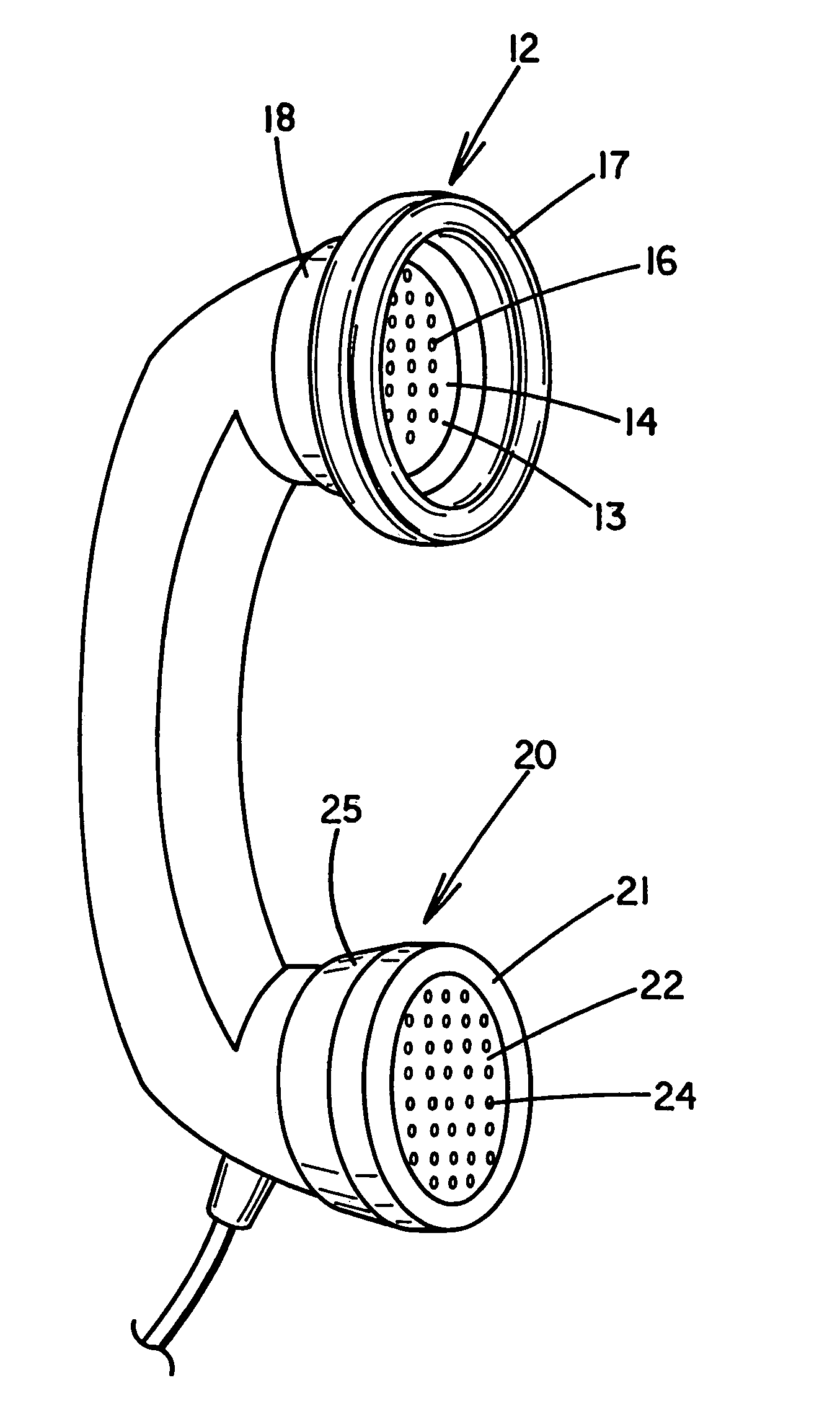
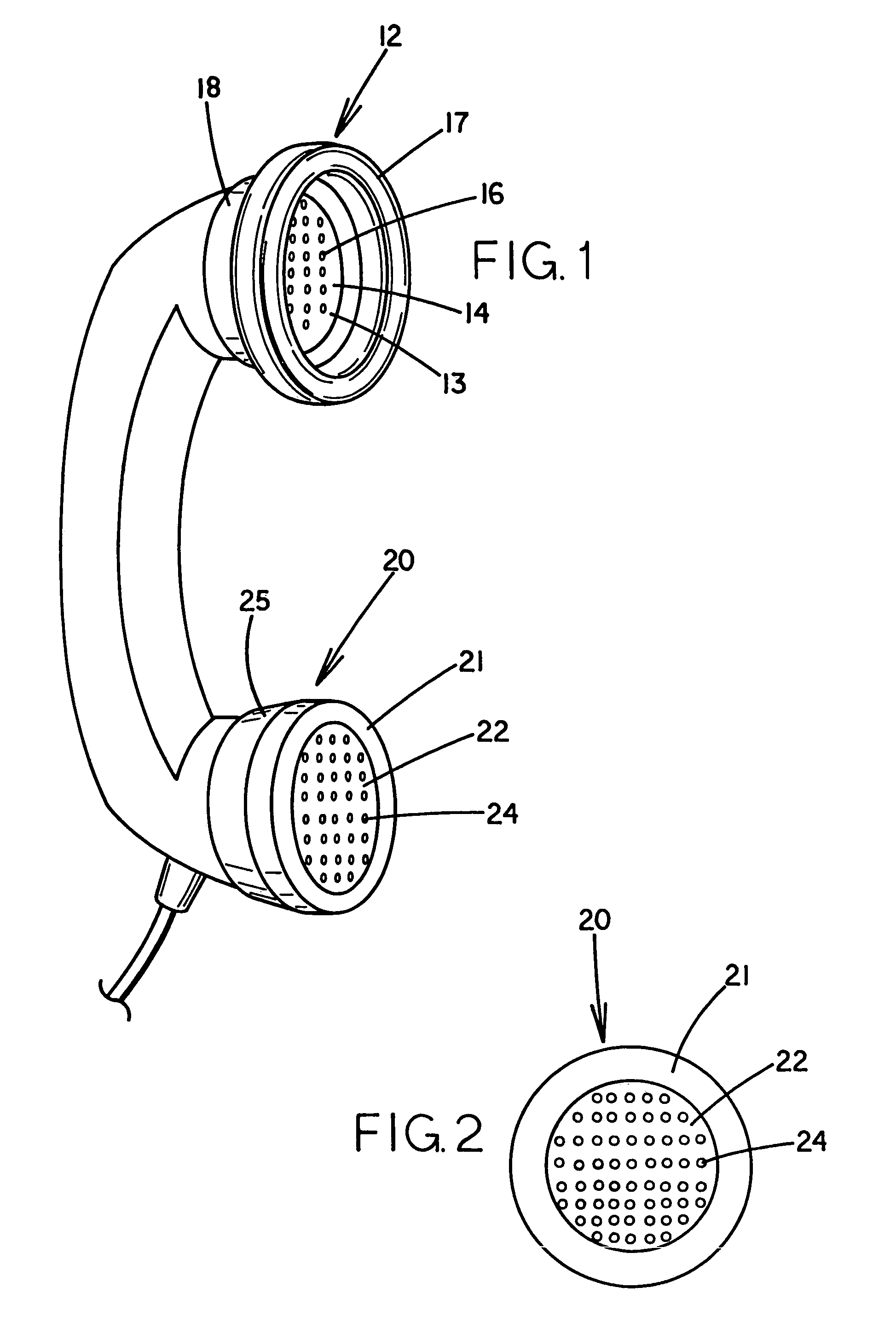
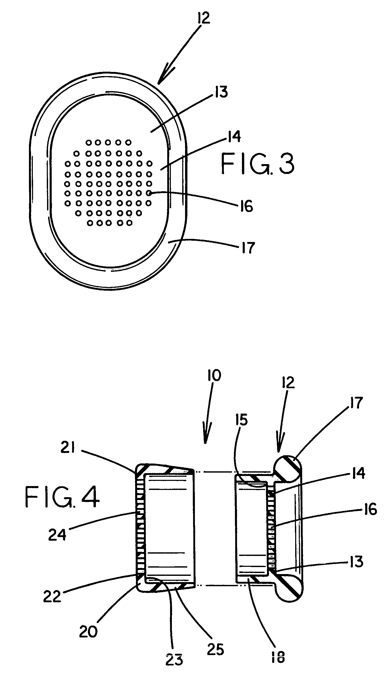
[0034]With reference now to the drawings, and in particular to FIGS. 1 through 8 thereof, a new telephone mouthpiece and earpiece cover system embodying the principles and concepts of the present invention and generally designated by the reference numeral 10 will be described.

[0035]As best illustrated in FIGS. 1 through 4, the telephone mouthpiece and earpiece cover system 10 generally comprises an earpiece cover attachment 12 and a mouthpiece cover attachment 20. The earpiece cover attachment 12 comprises a base 13 having a plurality of holes 16 extending therethrough. The front surface 14 of the base 13 of the earpiece attachment has an annular lip 17 extending around the outer perimeter of the base 13 of the earpiece cover attachment 12. The back surface 15 of the base 13 of the earpiece cover attachment 12 has a perimeter wall 18 defining a space adapted for inserting the earpiece of a telephone therein. The mouthpiece cover attachment 20 comprises a top 21 with a plurality of a...


PUM


Abstract

A telephone mouthpiece and earpiece cover system for helping protect a user from contact from germs on a telephone. The system includes an earpiece cover attachment and a mouthpiece cover attachment. The earpiece cover attachment comprises a base having a plurality of holes extending therethrough. The front surface of the base of the earpiece attachment has an annular lip extending around the outer perimeter of the base of the earpiece cover attachment. The back surface of the base of the earpiece cover attachment has a perimeter wall defining a space adapted for inserting the earpiece of a telephone therein. The mouthpiece cover attachment comprises a top with a plurality of apertures extending therethrough. The back surface of the top of the mouthpiece cover attachment has an annular wall, which defines a space adapted for inserting a mouthpiece of a telephone therein.

Description

CROSS REFERENCE TO RELATED APPLICATION[0001]This application is a continuation-in-part of application Ser. No. 09 / 048,667, filed Mar. 26, 1998, now abandoned.BACKGROUND OF THE INVENTION[0002]1. Field of the Invention[0003]The present invention relates to telephone accessories and more particularly pertains to a new telephone mouthpiece and earpiece cover system for helping protect a user from contact from germs on a telephone.[0004]2. Description of the Prior Art[0005]The use of telephone accessories is known in the prior art. More specifically, telephone accessories heretofore devised and utilized are known to consist basically of familiar, expected and obvious structural configurations, notwithstanding the myriad of designs encompassed by the crowded prior art which have been developed for the fulfillment of countless objectives and requirements.[0006]Known prior art telephone accessories include U.S. Pat. No. 4,852,163; U.S. Pat. No. 3,169,171; PCT Patent No. WO 95 / 05723; U.S. Pa...

Claims


Application Information

Patent Timeline
IPC IPC(8): H04M1/00B08B3/00H04M9/00
CPCH04M1/17H04R1/12
Inventor ROBINSON, DAVE
Owner ROBINSON DAVE