Crankcase with bottom plate

a crankcase and bottom plate technology, applied in the direction of engine lubrication, mechanical equipment, pressure lubrication with lubrication pump, etc., to achieve the effect of preventing the release of lubricant to the ambient, reducing the number of seal structures of the crankcase, and ensuring the operation of safety

Active Publication Date: 2007-09-11
ROLLS ROYCE SOLUTIONS GMBH
View PDF16 Cites 4 Cited by
  • Summary
  • Abstract
  • Description
  • Claims
  • Application Information

AI Technical Summary

Benefits of technology

[0006]On a second section of the top side of the bottom plate, which is disposed within the crankcase, the pumps are arranged. Since the chamber at the bottom side of the crankcase is open, the pumps can be arranged on the top side of the bottom plate in such a way that they are arranged within the chamber. With the double wall structure, a lubricant release to the ambient is effectively prevented, that is, the operational safety is ensured.
[0007]In the bottom plate, the media flow channels, the lubricant storage chamber and the suction location for the pumps are disposed. By an integration of the fluid communication channels into the bottom plate, the number of seal structures of the crankcase is reduced. The auxiliary components are preassembled on the bottom plate so that they can be mounted to the bottom side of the crankcase together with the bottom plate in a single assembly step. This also improves the servicing capability. For the venting of the chamber, a channel extends from the geodetically highest point of the chamber to the suction sides of the pumps. Because of the high location of the suction location, a very good operating capability of the engine in an inclined position is achieved, it may be inclined for example up to 32″ side inclination. An oil-air mixture in the vent channel is sucked out by the pumps whereby the oil discharge of an oil separator of the engine is reduced.

Problems solved by technology

Since, in practice, the available construction space and the power output of the engine is given to the manufacturer by the final customer, the inclined crankcase causes a target conflict between the two requirements.

Method used


Image

  • Crankcase with bottom plate
  • Crankcase with bottom plate
  • Crankcase with bottom plate

Examples


Embodiment Construction

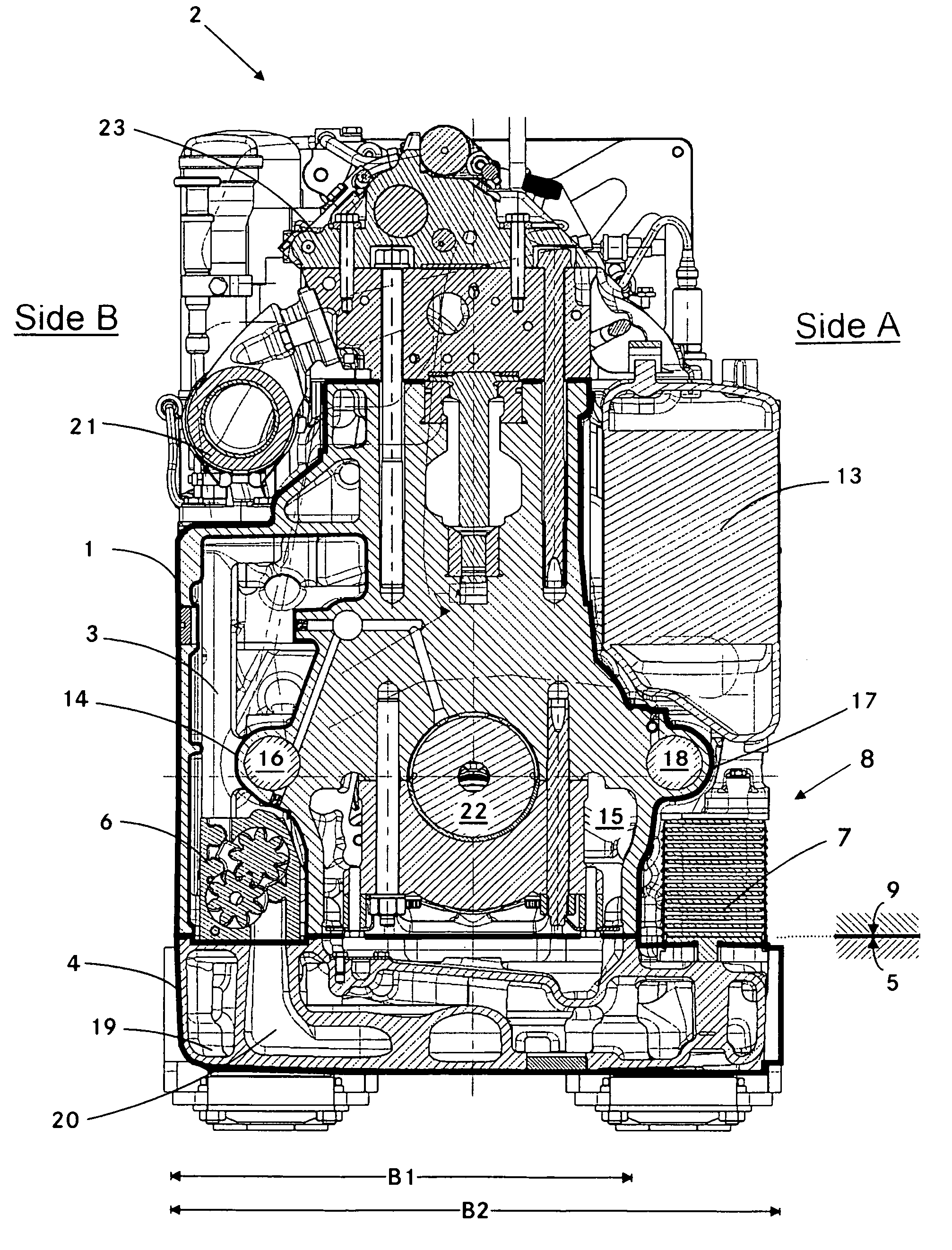
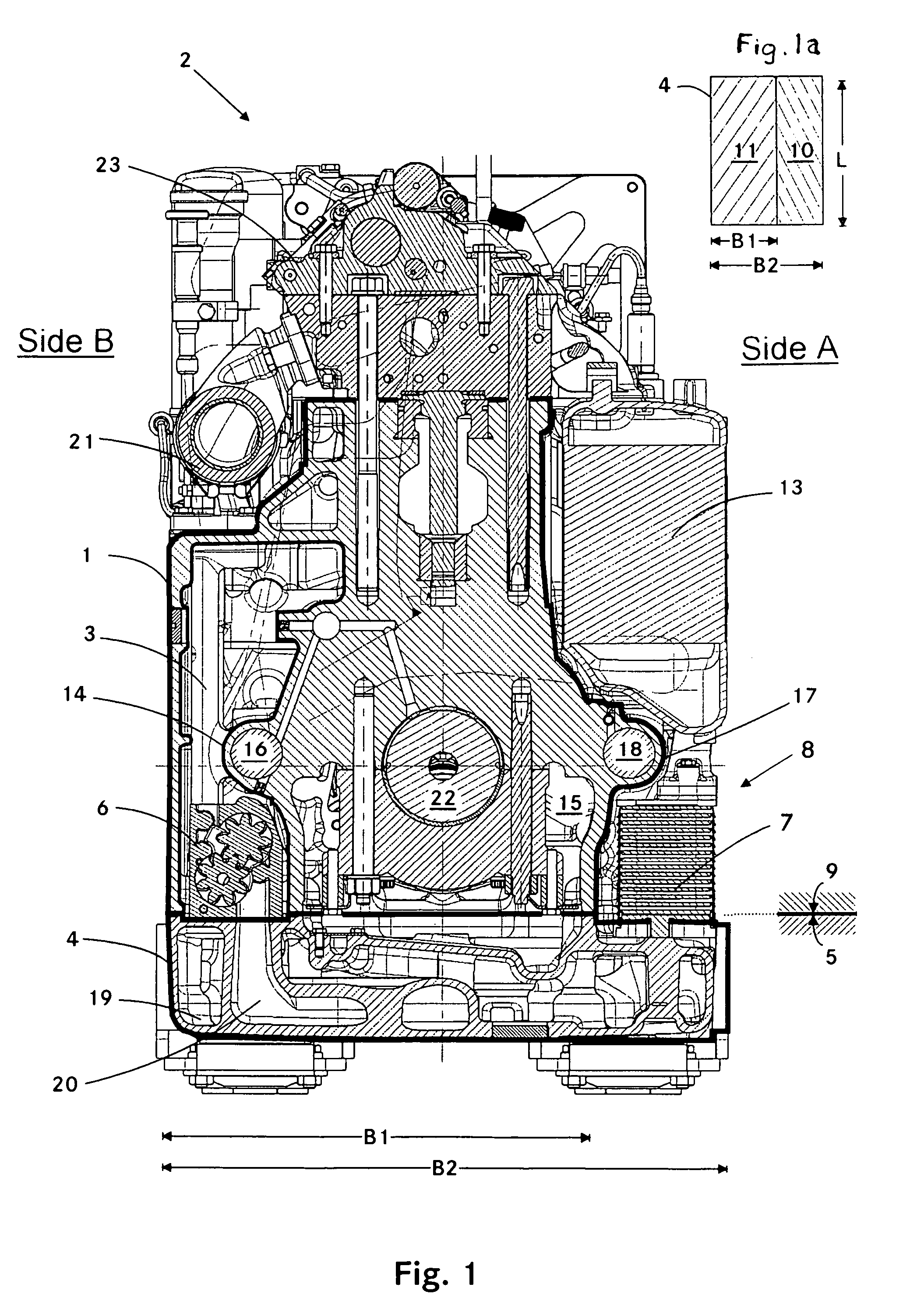
[0012]FIG. 1 shows a first cross-sectional view of an internal combustion engine 2 with in-line arrangement of the cylinders which are vertically oriented. The engine 2 includes a crankcase 1 which is closed toward the ambient by a bottom plate 4. The bottom plate 4 has a top side 9 which abuts the underside 5 of the crankcase. Within the crankcase 1, there is a chamber 3 for collecting lubricant. As shown in FIG. 1, the chamber 3 is disposed on a B-side of the internal combustion engine 2. At the bottom side 5 of the crankcase, the chamber 3 is open.

[0013]The bottom plate 4 includes the channels for conducting fluids, suction locations for the pumps 6 and lubricant storage chambers. The reference numeral 29 for example designates such a lubricant storage space and the reference numeral 20 designates a suction channel which extends from a suction location (not shown) to the pumps 6. By way of the bottom plate 4, a dry sump lubrication system is provided.

[0014]In accordance with the ...


PUM


Abstract

In a crankcase for an internal combustion engine, including a lubricant chamber for the collection of lubricant, and a bottom plate for providing dry sump lubrication closing the crankcase and being sealingly joined to the bottom end of the crankcase, wherein the crankcase includes auxiliary equipment comprising pumps for pumping lubricant into the lubricant chamber and from the lubricant chamber to various lubrication points, the bottom plate has a width exceeding the width of the crankcase so that it forms a section which is disposed outside the crankcase and auxiliary equipment is disposed on this section outside the crankcase.

Description

BACKGROUND OF THE INVENTION[0001]The present invention resides in a crankcase for an internal combustion engine with in-line cylinder arrangement, including a chamber for collecting lubricant which is arranged within the crankcase, and with a bottom plate for providing dry sump lubrication, which bottom plate closes the crankcase to the ambient.[0002]DE 21 40 377 A discloses a crankcase for an internal combustion engine with in-line cylinder arrangement wherein a side-wall of the crankcase is provided at the side of the cylinders in the form of a chamber. Toward the ambient, the crankcase is closed at the bottom by an oil pan. From the oil pan, a suction pump pumps the lubricant into the chamber whereby a dry-sump lubrication system is provided. The cylinder head includes several channels by which the cylinder head is in communication with the chamber. The lubricant flowing back from the lubricating locations of the cylinder head is conducted directly into the chamber while bypassin...

Claims


Application Information

Patent Timeline
Patent Type & Authority Patents(United States)
IPC IPC(8): F01M1/12
CPCF01M11/0004F02F7/0007F01M2001/126F01M11/00F02F7/00
Inventor HUSTER, JOACHIMNEU, DAGMAR
Owner ROLLS ROYCE SOLUTIONS GMBH
Why Eureka
Try Eureka