Cold-performance fluidic oscillator

a fluidic oscillator, cold technology, applied in the direction of combustion types, transportation and packaging, lighting and heating apparatus, etc., can solve the problems of no longer providing a jet and the performance of this type of oscillator can deteriora

Active Publication Date: 2007-09-11
DLHBOWLES INC
View PDF23 Cites 97 Cited by
  • Summary
  • Abstract
  • Description
  • Claims
  • Application Information

AI Technical Summary

Problems solved by technology

However, it also has been found that, as the temperature of such liquids continues to decrease so as to cause their viscosity to increase (e.g., 25 centipoise), the performance of this type of oscillator can deteriorate to the point where it no longer provides a jet that is sufficiently oscillatory in nature to allow its spray to be distributed over an appreciable fan angle.
This situation is especially problematic in windshield washer applications that utilize such fluidic oscillators.

Method used


Image

  • Cold-performance fluidic oscillator
  • Cold-performance fluidic oscillator
  • Cold-performance fluidic oscillator

Examples


Embodiment Construction

[0032]Before explaining at least one embodiment of the present invention in detail, it is to be understood that the invention is not limited in its application to the details of construction and to the arrangements of the components set forth in the following description or illustrated in the drawings. The invention is capable of other embodiments and of being practiced and carried out in various ways.

[0033]Also, it is to be understood that the phraseology and terminology employed herein are for the purpose of description and should not be regarded as limiting. For example, the discussion herein below generally relates to liquid spray techniques; however, it should be apparent that the inventive concepts described herein are applicable also to the dispersal of other fluids, including gases, fluidized solid particles, etc.

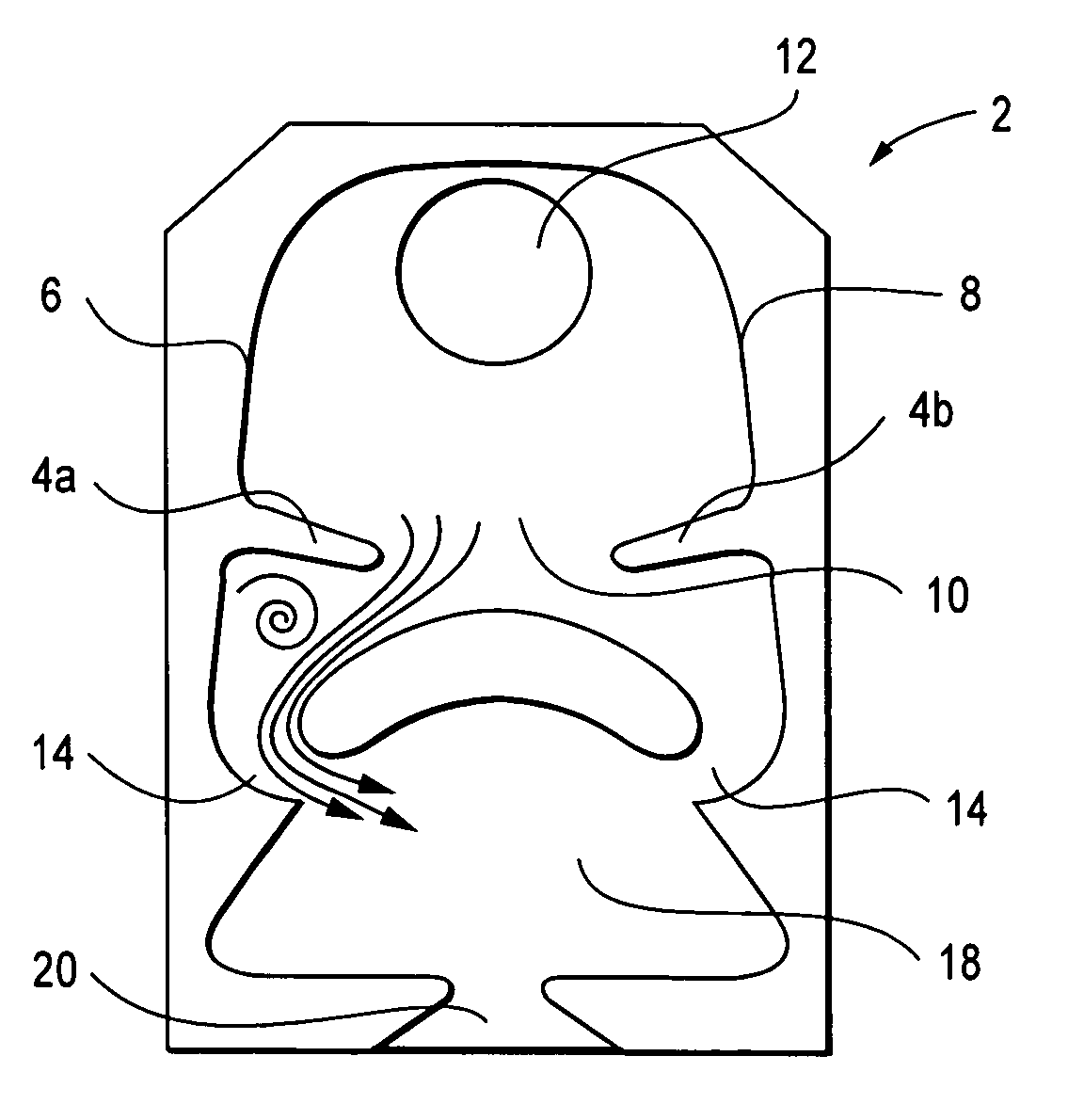
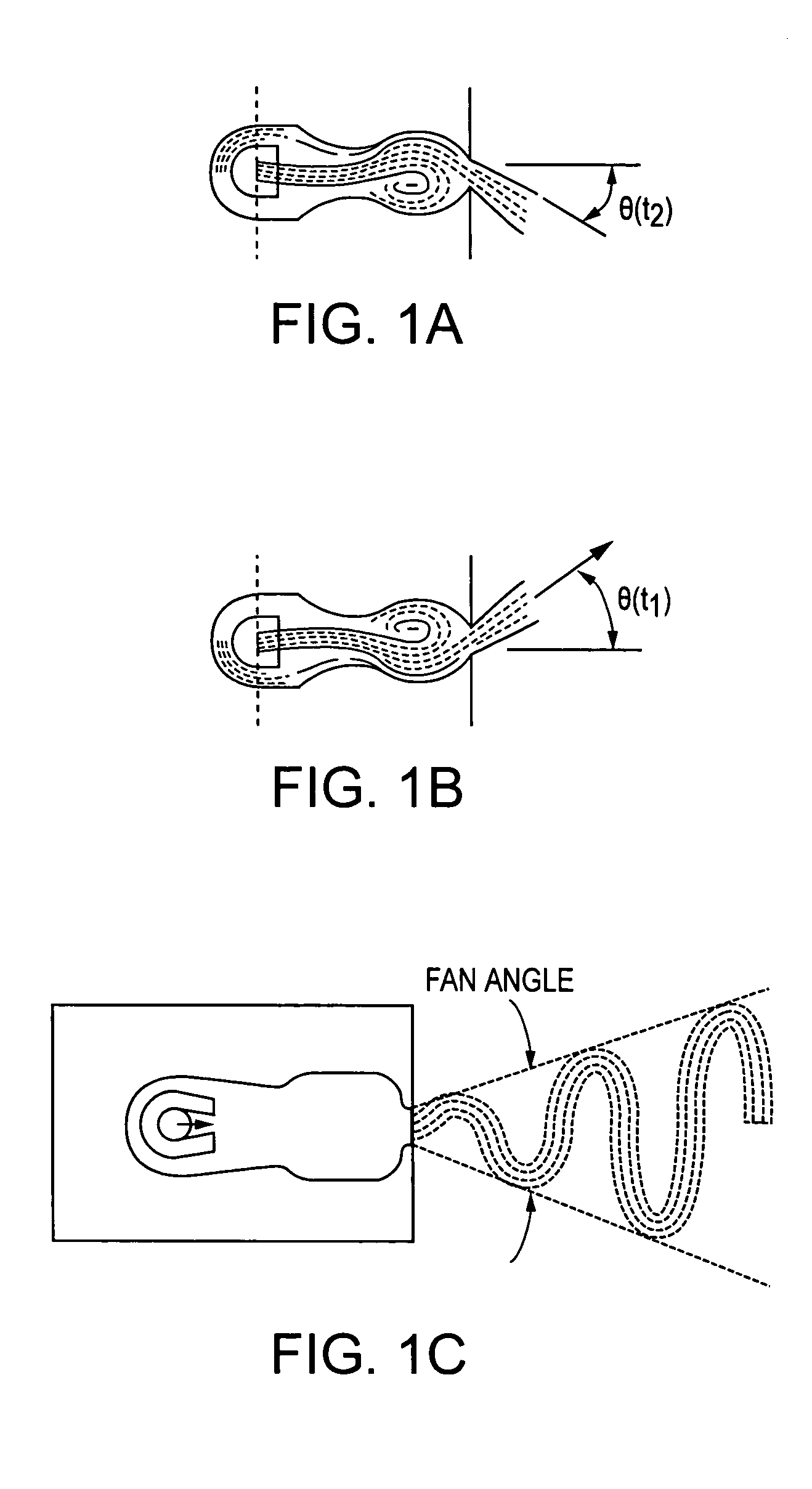
[0034]The present invention involves methods for creating fluidic oscillators of the type that are suitable for generating oscillating, fluid jets having very disti...


PUM


Abstract

A fluidic oscillator suitable for use at colder temperatures for generating an exhaust flow in the form of an oscillating spray of fluid droplets has an inlet for pressurized fluid, a pair of power nozzles configured to accelerate the movement of the pressurized fluid, a fluid pathway that connects and allows for the flow of pressurized fluid between its inlet and the power nozzles, an interaction chamber which is attached to the nozzles and receives the flow from the nozzles, a fluid outlet from which the spray exhausts from the interaction chamber, and a means for increasing the instability of the flow from the power nozzles, with this means being situated in a location chosen from the group consisting of a location within the fluid pathway or proximate the power nozzles. In a first preferred embodiment, the flow instability generating means comprises a protrusion that extends inward from each side of the fluid pathway so as to cause a flow separation region downstream of the protrusions. In a second preferred embodiment, the flow instability generating means comprises a step in the height elevation of the floor of the power nozzles with respect to that of the interaction chamber.

Description

BACKGROUND OF THE INVENTION[0001]1. Field of the Invention[0002]This invention relates to fluid handling processes and apparatus. More particularly, this invention relates to a fluidic oscillator that can operate at the colder temperatures usually associated with higher viscosity fluids.[0003]2. Description of the Related Art[0004]Fluidic oscillators are well known in the prior art for their ability to provide a wide range of liquid spray patterns by cyclically deflecting a liquid jet. The operation of most fluidic oscillators is characterized by the cyclic deflection of a fluid jet without the use of mechanical moving parts. Consequently, an advantage of fluidic oscillators is that they are not subject to the wear and tear which adversely affects the reliability and operation of other spray devices.[0005]Examples of fluidic oscillators may be found in many patents, including U.S. Pat. Nos. 3,185,166 (Horton & Bowles), 3,563,462 (Bauer), 4,052,002 (Stouffer & Bray), 4,151,955 (Stouf...

Claims


Application Information

Patent Timeline
Patent Type & Authority Patents(United States)
IPC IPC(8): B05B1/08B05B17/04F15C1/08
CPCB05B1/08F15B21/12Y10S239/03Y10T137/2185
Inventor GOPALAN, SHRIDHARRUSSELL, GREGORY
Owner DLHBOWLES INC
Why Eureka
Try Eureka