Multi-function binding system

a multi-functional, binding technology, applied in the field of bindings, can solve the problems of increasing the potential of ski bindings, complex mechanisms used in ski bindings, and riders not being able to reach the binding straps in order to remove the board

Inactive Publication Date: 2007-09-11
MILLER SPORTS INT
View PDF21 Cites 30 Cited by
  • Summary
  • Abstract
  • Description
  • Claims
  • Application Information

AI Technical Summary

Benefits of technology

[0011]The present invention also features a binding system for use on a sliding board comprising: (a) a binding operable with a boot assembly, the binding comprising a support surface and toe and heel pieces extending therefrom, the toe and heel pieces each having a receiver formed therein; (b) a base assembly configured to be rotatably and removably secured to a deck of a sliding board and to releasably couple and support the binding during use of the sliding board, the base assembly comprising: (i) a support disc configured to be removably coupled to the deck of the sliding board and to secure the base assembly to the sliding board; (ii) a deck plate rotatable about the support disc and configured to be positioned adjacent the deck; (iii) a bonnet also rotatable about the support disc and configured to receive and engage the binding, the bonnet operable with the deck plate to support one or more components of the base assembly; (iv) adjustment means for facilitating the rotational adjustment of the bonnet and the deck plate about the support disc, thereby facilitating a plurality of stance orientations of the boot assembly with respect to the sliding board, the adjustment means configured to selectively engage the support disc at any one of a plurality of adjustment positions; (v) release means for facilitating the selective manual release of the binding from the base assembly, and therefore the boot assembly from the sliding board; (vi) a toe plunger supported about a front portion of the bonnet and operable with the release means, the toe plunger being configured to releasably engage the receiver formed in the toe piece of the binding to secure the binding to the base assembly; and (vii) a heel plunger supported about a rear portion of the bonnet and operable with the release means, the heel plunger being configured to releasably engage the receiver formed in the heel piece of the binding.
[0014]Each of the rider's feet are held in place by a boot system operable with the binding. Each binding is configured to engage the base assembly by fitting the binding over the bonnet and causing the toe and heel plungers to engage the binding, thus securing it in place. In other words, the binding system allows the rider to “step-in” to the binding system simply by placing a foot into the boot assembly, positioning the binding over the base assembly, and applying a downward force to snap the binding in place down onto the base assembly, with the toe and heel plungers engaging and releasably coupling the binding. The base assembly further functions to provide a riser function to improve the performance of the sliding board.
[0015]Unlike prior related snowboard binding systems, the present invention binding system will release upon impact. This function is made possible by an adjustable tension release system that may be pre-set by the rider to meet desired specifications. The tension in the binding system is pre-set on at least one, and preferably both, of the toe and heel plungers using a separate spring and shaft system for each toe and heel plunger. The current release tension setting may be viewed through a window formed in the bonnet of the base assembly, which window is shaped and designed to cover the inner functioning mechanisms of the base assembly and to protect these from snow and ice, while still allowing the toe and heel plungers to extend outside the bonnet.
[0017]In addition, the toe and heel plungers comprise a specific design to facilitate an infinite number of release angles. This is accomplished by forming at least one, and preferably a plurality, of pressure surfaces in the toe and heel plungers. The pressure surfaces are formed on pressure angles, preferably between 35° and 40°. Providing infinite release angles allows the binding to release from the base assembly at any angle from the horizontal line upward.
[0019]The adjustment means may also comprise a quick-release design, wherein the adjustment means comprises a lever located or positioned on a side of the bonnet opposite from the quick-release release lever. The lever may be configured to releasably engage all or a portion of the support disc, thereby facilitating a plurality of different stance orientations as desired by the rider without requiring the unscrewing of any screws or other similar fasteners.

Problems solved by technology

Unfortunately, the safety aspects of snowboarding equipment lag behind that developed for skiing, particularly with respect to the binding systems provided to secure the snowboard to the feet of the rider.
With the snowboard unreleased and still attached to the rider's feet, the length of the snowboard can act as an anchor in the event of a snow slide or avalanche, and once covered in snow the rider may not be able to reach the binding straps in order to remove the board.
Another difficulty associated with snowboard bindings occurs where the rider wishes to use a ski lift or tow to return to the top of a mountain slope.
However, in order to provide adequate and safe release, or tension release, complex mechanisms are employed within the ski bindings.
These complex mechanisms typically provide only a limited number of release angles, thus increasing the potential that an impact or other force will not trigger a justified release.
Another problem with prior related bindings is that there is no interchangeability between the types of sliding boards, thus increasing the expense of participating in more than one sliding sport.

Method used


Image

  • Multi-function binding system
  • Multi-function binding system
  • Multi-function binding system

Examples


Embodiment Construction

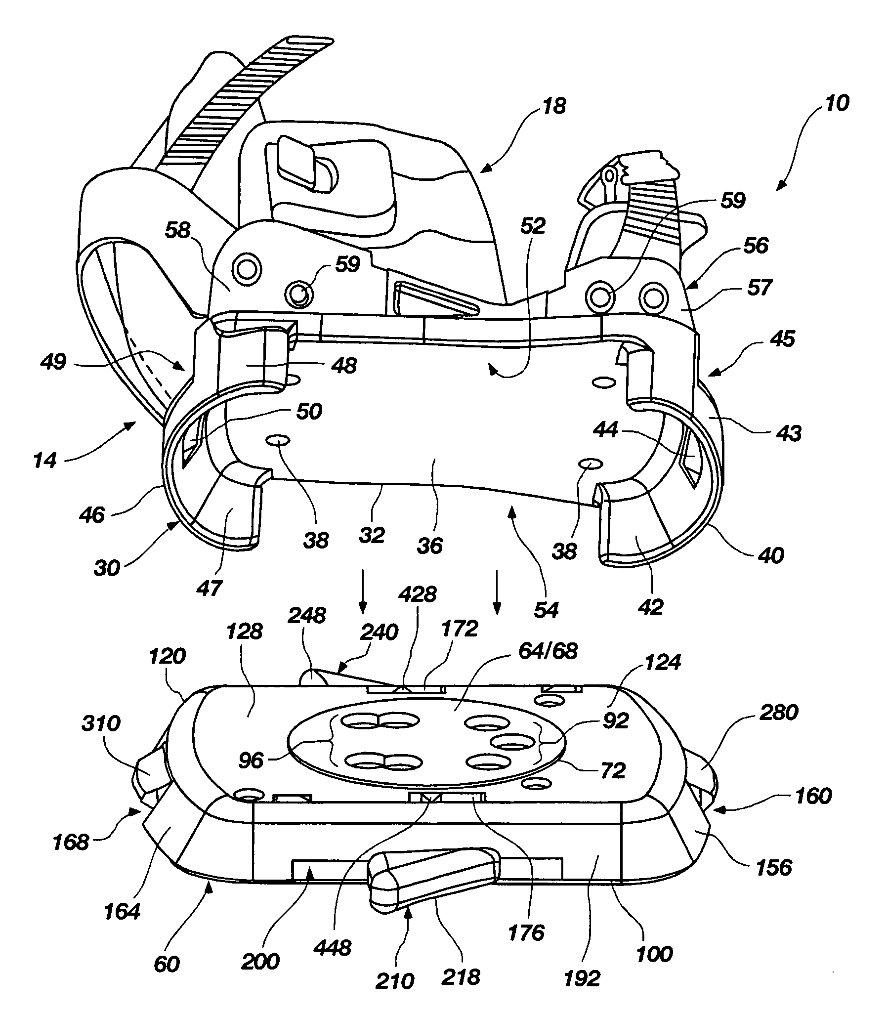
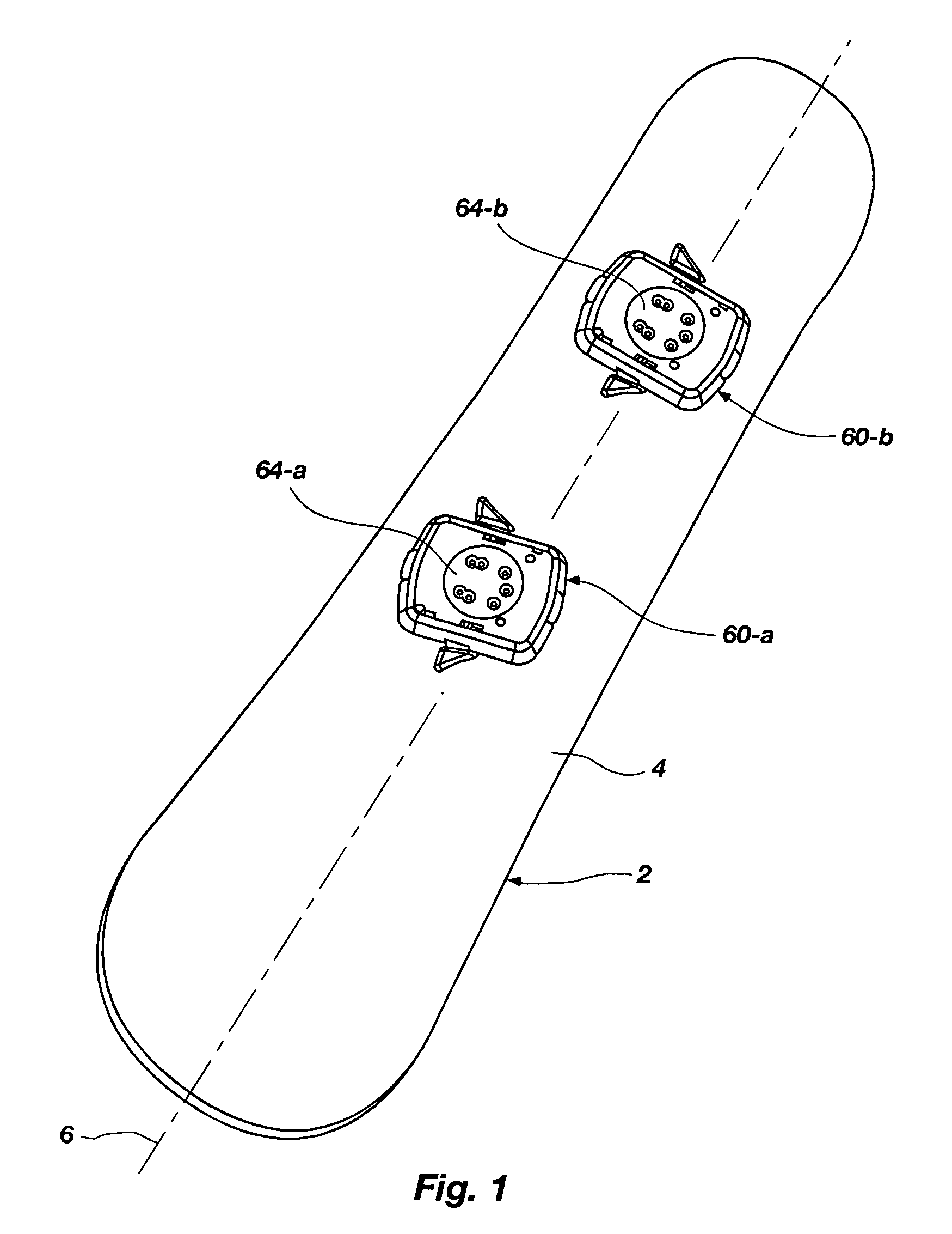
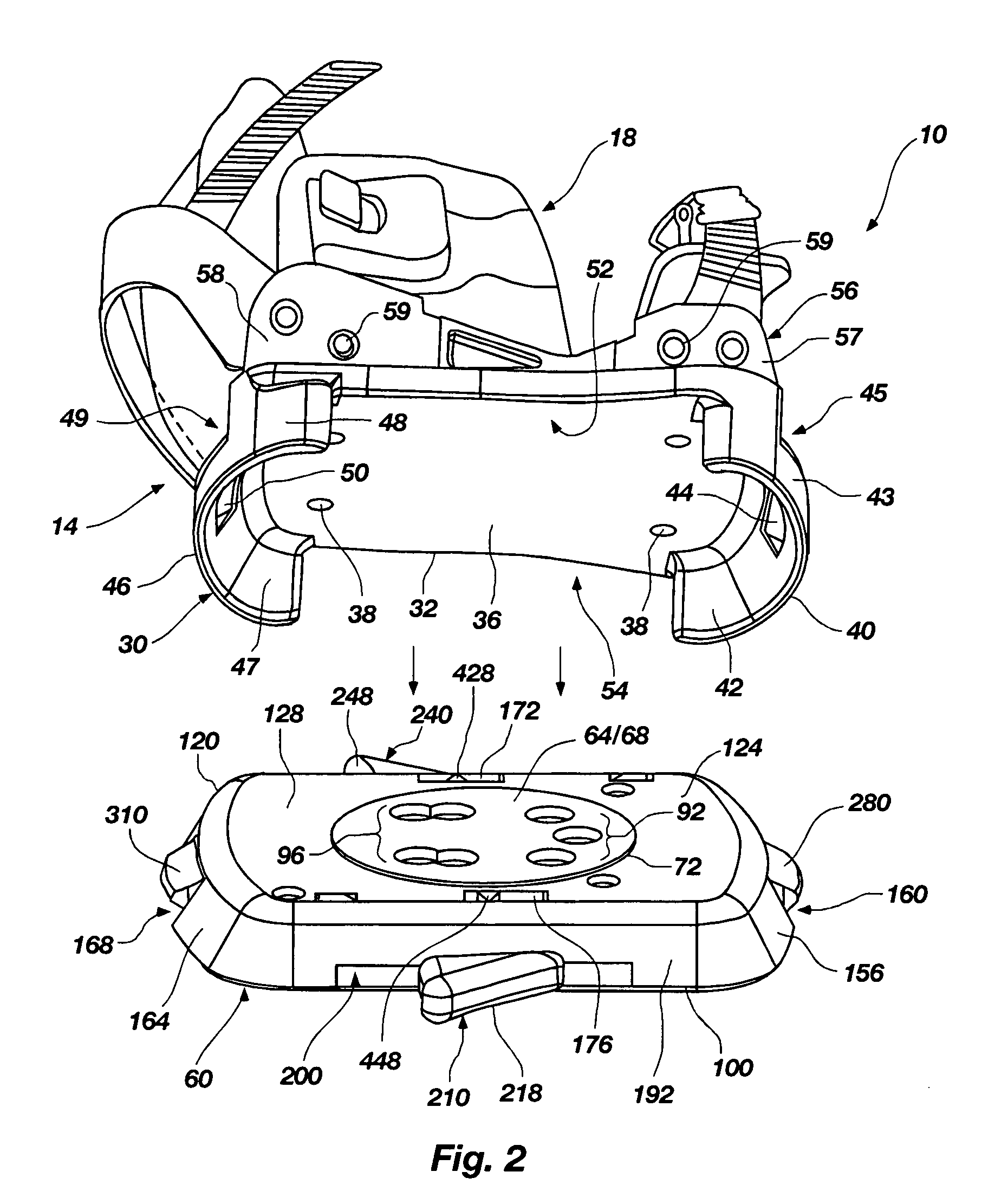
[0039]The following detailed description of exemplary embodiments of the invention makes reference to the accompanying drawings, which form a part hereof and in which are shown, by way of illustration, exemplary embodiments in which the invention may be practiced. While these exemplary embodiments are described in sufficient detail to enable those skilled in the art to practice the invention, it should be understood that other embodiments may be realized and that various changes to the invention may be made without departing from the spirit and scope of the present invention. Thus, the following more detailed description of the embodiments of the present invention, as represented in FIGS. 1 through 14, is not intended to limit the scope of the invention, as claimed, but is presented for purposes of illustration only and not limitation to describe the features and characteristics of the present invention, to set forth the best mode of operation of the invention, and to sufficiently e...


PUM


Abstract

A multi-function binding system configured for use on a sliding board comprising: (a) a binding operable with a boot assembly, the binding comprising a support surface and toe and heel pieces; (b) a base assembly rotatably and removably secured to a deck of a sliding board and to releasably couple the binding, the base assembly comprising: (i) a support disc removably coupled to the deck of the sliding board and to secure the base assembly to the sliding board; (ii) a deck plate rotatable about the support disc and configured to be positioned adjacent the deck; (iii) a bonnet also rotatable about the support disc and configured to receive and engage the binding; (iv) an adjustment mechanism for rotational adjustment of the bonnet and the deck plate about the support disc with respect to the sliding board; (v) a coupler mechanism configured to releasably couple the binding to the base assembly, and therefore the boot system to the sliding board, thereby securing a user thereto; and (vi) a release for actuating the coupler to release the binding from the base assembly, and therefore the the boot system from the sliding board.

Description

RELATED APPLICATIONS[0001]This application is a continuation-in-part application that claims priority to U.S. Provisional Application No. 60 / 579,526, filed Jun. 15, 2004, and entitled, “EZ multi-function release binding for boards and skis,” which is incorporated by reference herein in its entirety. This continuation-in-part application further claims priority to U.S. patent application Ser. No. 10 / 467,941, filed Aug. 14, 2003 now U.S. Pat. No. 7,178,821, and titled, “Universal Ski and Snowboard Binding,” which claims priority to PCT Application No. PCT / US02 / 05174, filed Feb. 15, 2002, and titled, “Universal Ski and Snowboard Binding,” which claims priority to U.S. Provisional Patent Application Nos. 60 / 268,542, filed Feb. 15, 2001, and titled, “Z Release System;” 60 / 268,541, filed Feb. 15, 2001, and titled, “Breakaway Interface;” and 60 / 348,274, filed Jan. 15, 2002, and titled, “Z Combo Release & Conversion System,” each of which are incorporated by reference herein in their entire...

Claims


Application Information

Patent Timeline
Patent Type & Authority Patents(United States)
IPC IPC(8): A63C9/00B62B13/00
CPCA63C10/10A63C10/106A63C10/12A63C10/14A63C10/145A63C10/18A63C17/045B63B35/812A63C10/04A63C10/24B63B32/35B63B32/47
Inventor MILLER, MATTHEW E.BARNEY, SHANE R.FOX, BRADY S.FURR, DOUGLAS K.
Owner MILLER SPORTS INT
Why Eureka
Try Eureka