RF device with thermo-electric cooler

a thermo-electric cooler and rf device technology, applied in the field of tissue treatment, can solve the problems of uniform thermal effect over the electrode surface, limitation of treatment effectiveness, and/or preclusion of treatment altogether, and achieve the effect of controlling the tissue

Inactive Publication Date: 2007-09-11
THERMAGE INC
View PDF349 Cites 135 Cited by
  • Summary
  • Abstract
  • Description
  • Claims
  • Application Information

AI Technical Summary

Problems solved by technology

However, these technologies have a number of technical limitations and clinical issues which limit the effectiveness of the treatment and / or preclude treatment altogether.
Edge effects cause problems in treating the skin for several reasons.
First, they result in a non-uniform thermal effect over the electrode surface.
However, this point design is undesirable for creating a reasonably gentle thermal effect over a large surface area.
As is discussed below, a non-uniform thermal pattern makes cooling of the skin difficult and hence the resulting treatment process as well.
However, cooling of the skin is made difficult if there is a non-uniform heating pattern.
Contrarily, if the cooling effect is decreased to the point where there is a good thermal effect in the center of the electrode, then there probably will not be sufficient cooling to protect tissue in contact with the edges of the electrode.
As a result of these limitations, in the typical application of a standard electrode there is usually an area of non-uniform treatment and / or burns on the skin surface.
For this and related applications, if the collagen contraction and resulting skin tightening effect are non-uniform, then a medically undesirable result may occur.

Method used


Image

  • RF device with thermo-electric cooler
  • RF device with thermo-electric cooler
  • RF device with thermo-electric cooler

Examples


Embodiment Construction

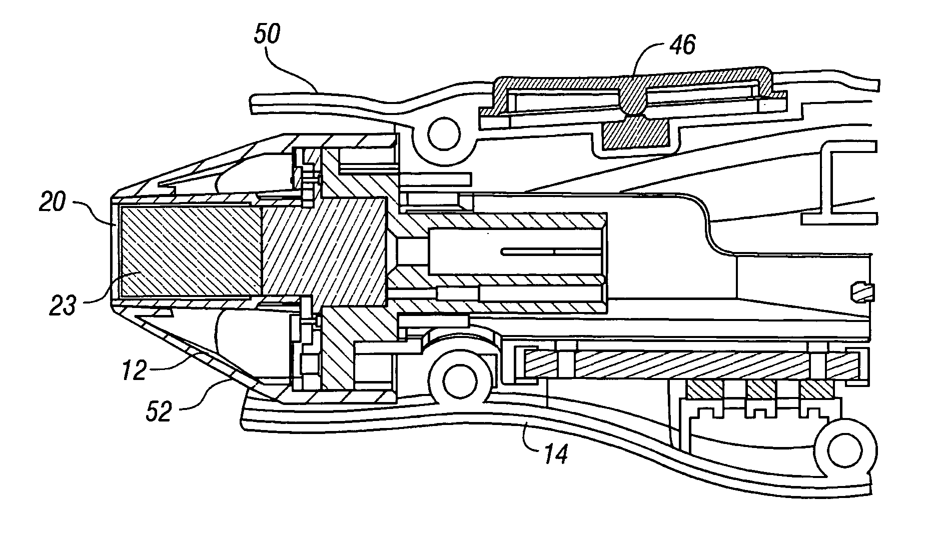
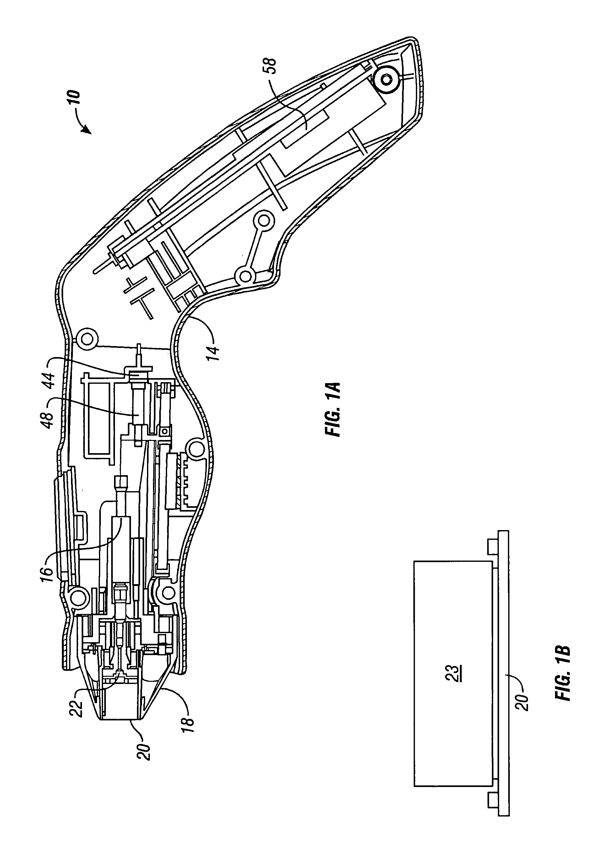
[0052]In various embodiments, the present invention provides methods for treating a tissue site. In one embodiment, an energy delivery surface of an energy delivery device is coupled to a skin surface. The coupling can be a direct, in contact, placement of the energy delivery surface of the energy delivery on the skin surface, or distanced relationship between the two with our without a media to conduct energy to the skin surface from the energy delivery surface of the energy delivery device. The skin surface is cooled sufficiently to create a reverse thermal gradient where a temperature of the skin surface is less than an underlying tissue. Energy is delivered from the energy delivery device to the underlying tissue area, resulting in a tissue effect at the skin surface.

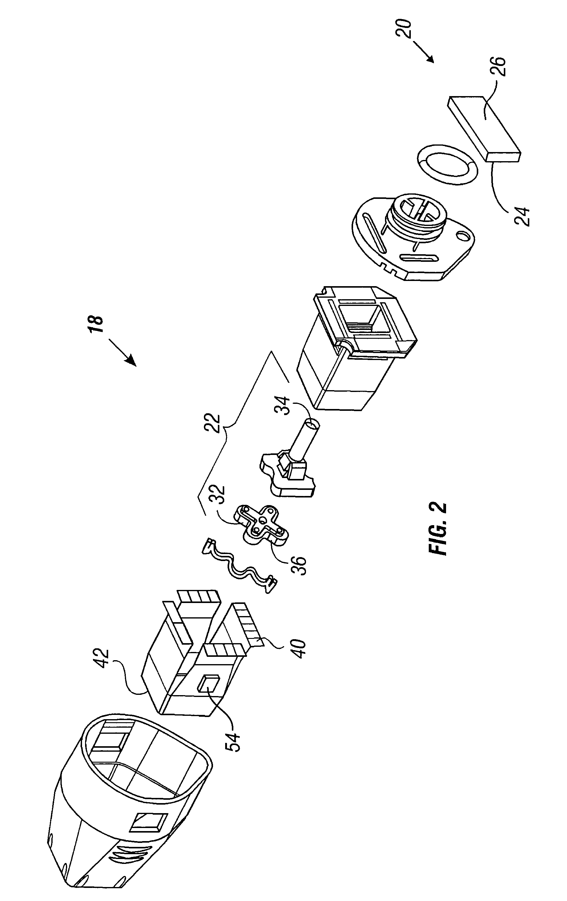
[0053]Referring now to FIG. 1(a), the methods of present invention can be achieved with the use of a handpiece 10. Handpiece 10 is coupled with a handpiece assembly 12 that includes a handpiece housing 14 and a cool...


PUM


Abstract

An RF device includes a support structure. An RF electrode is coupled to the support structure and includes conductive and dielectric portions. A thermo-electric cooler is coupled to the support structure and is configured to cool a back surface of the RF electrode.

Description

CROSS-REFERENCE TO RELATED APPLICATIONS[0001]This application is a continuation-in-part of U.S. Ser. No. 10 / 072,475 filed Feb. 6, 2002 now U.S. Pat. No. 7,022,121 and a continuation-in-part of U.S. Ser. No. 10 / 072,610 filed Feb. 6, 2002 now U.S. Pat. No. 7,141,049 both of which are continuations-in-part of U.S. Ser. No. 09 / 522,275, filed Mar. 9, 2000, now U.S. Pat. No. 6,413,255, which claims the benefit of U.S. Ser. No. 60 / 123,440, filed Mar. 9, 1999. This application is also a continuation-in-part of U.S. Ser. No. 10 / 026,870, filed Dec. 20, 2001, now U.S. Pat. No. 6,749,624, which is a continuation of U.S. Ser. No. 09 / 337,015 filed Jun. 30, 1999, now U.S. Pat. No. 6,350,276, which is a continuation-in-part of U.S. Ser. No. 08 / 583,815, filed Jan. 5, 1996, now U.S. Pat. No. 6,241,753, U.S. Ser. No. 08 / 827,237, filed Mar. 28, 1997, now U.S. Pat. No. 6,430,446, U.S. Ser. No. 08 / 914,681, filed Aug. 19, 1997, now U.S. Pat. No. 5,919,219, and U.S. Ser. No. 08 / 942,274, filed Sep. 30, 1997...

Claims


Application Information

Patent Timeline
Patent Type & Authority Patents(United States)
IPC IPC(8): A61B18/18A41D13/005A45D44/22A61BA61B18/00A61B18/12A61B18/14A61B19/00A61F7/02A61H7/00A61H9/00A61N1/06A61N1/28A61N1/30A61N1/32A61N1/40A61N5/04A61N5/06
CPCA45D44/22A61B18/12A61B18/1206A61B18/14A61B18/148A61B19/24A61N1/0468A61N1/0472A61N1/06A61N1/28A61N1/30A61N1/328A61N1/40A61N1/403A61N5/04A61N5/0616A61B18/00A61B18/1402A61B2017/003A61B2018/00011A61B2018/00023A61B2018/00452A61B2018/00488A61B2018/0066A61B2018/00702A61B2018/00779A61B2018/00791A61B2018/00875A61B2018/1495A61B2019/464A61F2007/0021A61H7/001A61H9/005A61H9/0071A61H2201/10A61M2205/3606A61N2005/0645A61B2090/064A61B90/02
Inventor STERN, ROGER A.LEVINSON, MITCHELLWEBER, BRYAN
Owner THERMAGE INC
Why Eureka
Try Eureka