Biaxial artificial disc replacement

a technology of artificial discs and adrs, applied in the field of artificial disc replacement, can solve the problems of increasing the risk of separation of the adr from the vertebrae above and below, increasing the changes of the future, and increasing the risk of disc separation

Inactive Publication Date: 2007-09-11
FERREE BRET A
View PDF13 Cites 92 Cited by
  • Summary
  • Abstract
  • Description
  • Claims
  • Application Information

AI Technical Summary

Problems solved by technology

Consequently, the discs adjacent to the fused level are subjected to increased stress, which increases the changes of future surgery to treat the degeneration of the discs adjacent to the fusion.
Replicating the movements of the natural disc also decreases the risk of separation of the ADR from the vertebrae above and below the ADR.
Unfortunately, the flexibility of the hydrogel and the constraining jacket allow hydrogel ADRs to change shape and extrude through defects in the annulus through which the ADR was inserted, for example.
Metal and rubber ADRs, on the other hand, also frequently fail at the metal-rubber interface.
The rubber fails directly due to high shear stresses or because the rubber separates from the metal.

Method used


Image

  • Biaxial artificial disc replacement
  • Biaxial artificial disc replacement
  • Biaxial artificial disc replacement

Examples


Embodiment Construction

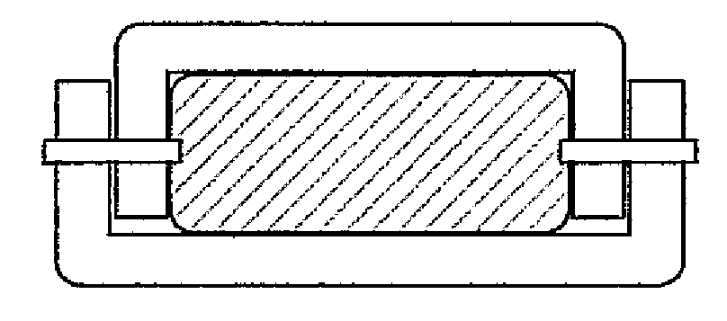
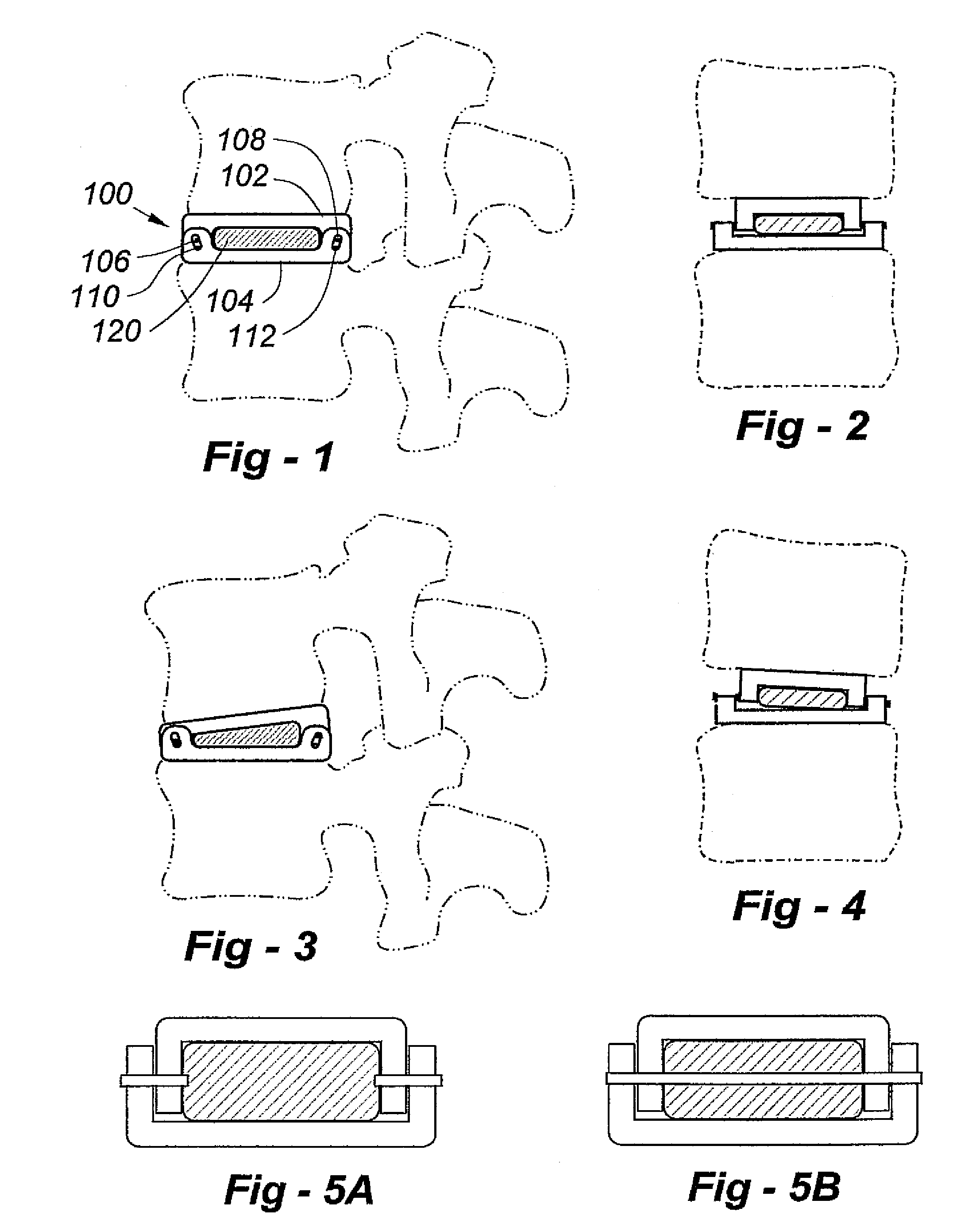
[0031]FIG. 1 is a view of the lateral aspect of the spine and an ADR according to the invention depicted generally at 100. A top endplate component 102 articulates with a bottom endplate component 104 through axles 106, 108 in the front and back of the ADR. A cushioning component 120 is disposed between the endplate components 102, 104. Holes 110, 112 of the bottom endplate component receive the axles 106, 108 and are sized to allow normal movements of the spine, preferably a limited amount of flexion, extension, lateral bending, and / or translocation. Depending upon the type and degree of desired movement, over-sized holes may be provided on the top endplate component, or both components 102, 104.

[0032]The endplate components are preferably made of metal, and the surface of each endplate component adjacent to the vertebrae would preferably incorporate a bone-ingrowth promoting surface of the types known to those skilled in orthopaedic design. The cushion component 120 would likely b...


PUM

PropertyMeasurementUnit
cross-sectional areasaaaaaaaaaa
degree of lateral bendingaaaaaaaaaa
forceaaaaaaaaaa

Abstract

An artificial disc replacement (ADR) is designed to protect a cushioning component from excessive force. Physical features on the front and back of the ADR enable the device to replicate the normal movements of the spine through predetermined, limited, movements of the endplate components relative to one another. For example, though not limited to these characteristics, the components of the ADR could be dimensioned to allow 15 degrees of flexion, 5 degrees of extension, 5 degrees of lateral bending, and 1-2 mm of translocation. In the preferred embodiment the physical features are axles that extend through overlapping lateral portions associated with the endplate components. A desirable configuration includes a pair of axles, one in the anterior portion and another in the posterior portion, wherein some or all of the axles extend through an oversized aperture that allows the limited relative movement of the endplate components. Alternatively, the anterior and posterior physical features may include mating projections and depressions to permit a desired degree of relative movement.

Description

REFERENCE TO RELATED APPLICATION[0001]This application claims priority from U.S. Provisional Patent Application Ser. No. 60 / 420,169, filed Oct. 22, 2002, the entire content of which is incorporated herein by reference.FIELD OF THE INVENTION[0002]This invention relates generally to artificial disc replacement (ADR) and, in particular, to ADRs including cushioning components to protect the implant from excessive force.BACKGROUND OF THE INVENTION[0003]Improvements in prosthetic intervertebral disc and joint replacement components, and related surgical procedures, have led to dramatic increases in implant longevity. Many artificial hip and knee components now last for twenty years or more due to improved materials and greater insight into movement, load distribution and wear characteristics.[0004]Many spinal conditions, including degenerative disc disease, can now be treated through artificial disc replacement (ADR), which has several advantages over spinal fusion. The most important ad...

Claims


Application Information

Patent Timeline
Patent Type & Authority Patents(United States)
IPC IPC(8): A61F2/44A61B17/02A61F2/00A61F2/30A61F2/46
CPCA61F2/4425A61B2017/0256A61F2/30767A61F2/4611A61F2002/30069A61F2002/30331A61F2002/30434A61F2002/30471A61F2002/30481A61F2002/30517A61F2002/30528A61F2002/30563A61F2002/30777A61F2002/30841A61F2002/30934A61F2002/443A61F2002/4622A61F2220/0025A61F2220/0033A61F2220/0041A61F2220/0091A61F2310/00395A61F2002/30433
Inventor FERREE, BRET A.
Owner FERREE BRET A
Why Eureka
Try Eureka