Cervical intervertebral prosthesis

a cervical vertebral and prosthesis technology, applied in the field of cervical vertebral prosthesis, can solve the problems of undesirable relative movement, and achieve the effect of preventing undesired transverse movement and minimizing the potential for irritation of adjacent organs

Inactive Publication Date: 2007-09-11
CERVITECH INC
View PDF32 Cites 65 Cited by
  • Summary
  • Abstract
  • Description
  • Claims
  • Application Information

AI Technical Summary

Benefits of technology

[0005]The dorsally directed force which the toothing exerts on the cover plate is effective only upon relative movement between the cover plate and the associated vertebral body. Such a relative movement is undesirable, because in normal circumstances one obviously expects absolute immobilization between the cover plate and the associated vertebral body. In fact, the teeth, which can be regarded as a macroscopic roughening, normally contribute to maintaining the immobilized state between the cover plate and the associated vertebral body. This can be further promoted by providing the prosthesis surface with a coating which promotes intimate connection between bone and prosthesis surface, for example with a microporous and / or bioactive material promoting bone growth.
[0008]The flange can be provided with openings for receiving fixation members, for example bone screws. However, in most cases this is not necessary. A design in which there are no such screw holes and in which the flange has a smaller height in order to be able only to exert its abutment function can even be particularly advantageous. This is because it affords the possibility of forming a recess in the vertebral body, which recess receives the flange. The result of this is that the prosthesis can be pushed so far dorsally in relation to the ventral alignment surface of the adjacent vertebral bodies that it cannot cause irritation of the esophagus or of any nerves or vessels extending there. The prosthesis can even remain completely behind this alignment surface and, viewed from the ventral direction, can thus be anchored completely in the area of the vertebral bodies. Doing without the screw holes also has the advantage that the flange can be given such a low height that the implant becomes very small and can be implanted through a narrow access channel, for example of an endoscope.
[0009]If the serrations are designed as ribs extending transversely in relation to the sagittal direction, there is a possibility of the cover plate shifting relative to the associated vertebral body in the direction of these ribs. This can be avoided by providing grooves or ribs which extend transversely in relation to the direction of the tooth ribs. The grooves permit ingrowth of bone substance and thereby prevent the undesired transverse movement. Any ribs provided are expediently self-cutting so that they penetrate into the surface of the vertebral body as the prosthesis is inserted.
[0010]The abutment surface does not necessarily have to be formed by a flange. Instead, projections oriented transversely in relation to the plane of the cover plates in many cases suffice. These projections should be arranged symmetrically in a pair in order to permit an orientation of the prosthesis coincident with the direction of the vertebral bodies. Forming the abutment surface on a pair of symmetrically arranged projections spaced apart from one another has the advantage that the ventral center area of the vertebral bodies, which in principle is expected to be in proximity to the esophagus, is free from prosthesis parts.
[0011]All the ventral margins and edges of the prosthesis should be well rounded-off in order to minimize their potential for possible irritation of adjacent organs.

Problems solved by technology

Such a relative movement is undesirable, because in normal circumstances one obviously expects absolute immobilization between the cover plate and the associated vertebral body.

Method used


Image

  • Cervical intervertebral prosthesis
  • Cervical intervertebral prosthesis

Examples


Embodiment Construction

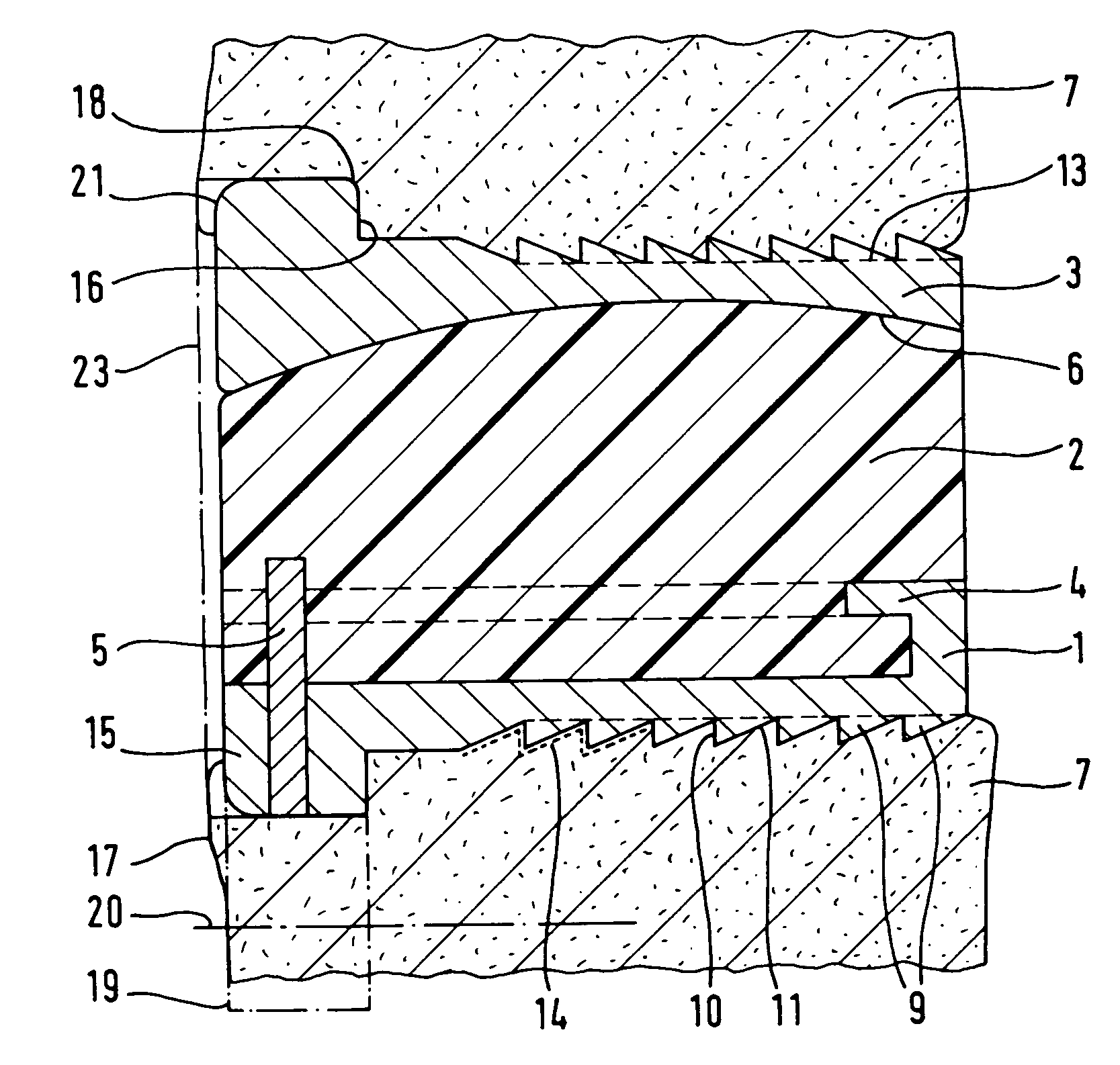
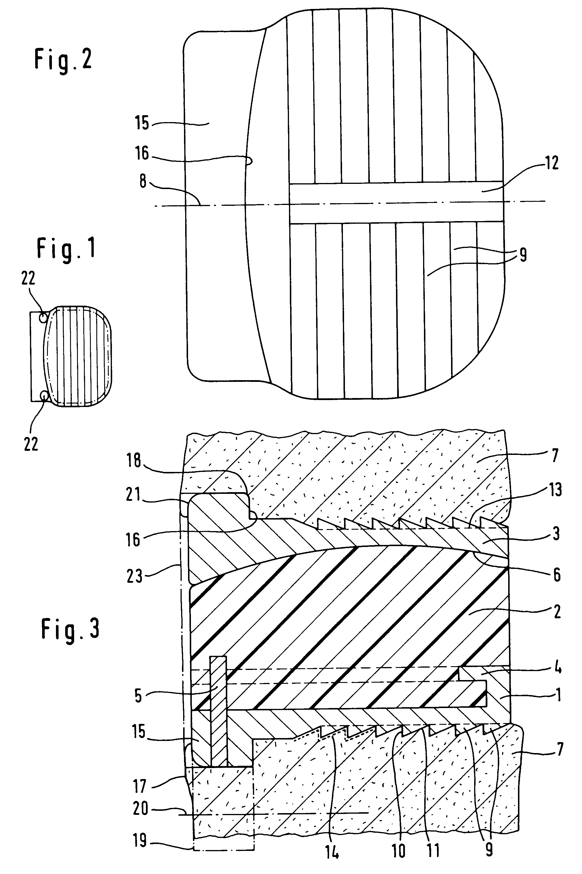
[0016]The prosthesis comprises a lower cover plate 1 of hard, resistant material, in particular metal, a prosthesis core 2 made of polyethylene or other plastic which has good sliding properties, and an upper cover plate 3 which is made of the same material as the lower cover plate 1. The prosthesis core 2 is connected to the lower cover plate 1 firmly, albeit also detachably. The connection is effected by undercut ledges 4 on the dorsal side and both lateral sides of the lower cover plate 1, into which the prosthesis core 2 provided with complementary grooves can be pushed. In the pushed-in position, it is secured by a bolt 5. The prosthesis core 2 and the upper cover plate 3 form interacting, complementary, preferably spherical slide surfaces 6.

[0017]Those surfaces of the cover plates 1 and 3 each facing the associated vertebral body 7 are designed the same. The greater part of their surface is covered by a multiplicity of teeth 9 which are of serrated design, namely with a steep ...


PUM


Abstract

A cervical intervertebral prosthesis includes two cover plates which are each configured to be connected to adjacent vertebral bodies. At least one of the two cover plates has a toothed portion which faces toward the vertebral body and whose teeth have a steep, ventrally directed flank and a less steep, dorsally directed flank. When the prosthesis is fitted with sufficient pressing between its adjacent vertebral bodies, the combination of the serrated toothed portion and the abutment surface is sufficient to hold the prosthesis securely in the desired position. In many cases this makes it possible to dispense with additional screw fixation. The flange carrying the abutment surface is in this case expediently shortened so that it can be accommodated in a recess of the bone so that the prosthesis does not protrude ventrally beyond the ventral alignment surface of the adjacent vertebral bodies.

Description

FIELD AND BACKGROUND OF THE INVENTION[0001]In the cervical region of the vertebral column, there is only a small amount of space available for receiving intervertebral prostheses. Even a slight shifting of prosthesis parts in the dorsal direction can affect the nerves of the spinal cord. Secure fixation of the prostheses is therefore of great importance. In the case of intervertebral prostheses for the lumbar region of the vertebral column, it is known for the cover plates of the prosthesis which face the adjacent vertebral bodies to be provided with ribs or projections which engage in prepared grooves in the vertebral bodies or are designed to be sharp and self-cutting. This is made possible by the fact that the vertebral bodies of the lumbar vertebral column are relatively large and high, so that there is enough space available for fixation devices of this kind. This also applies to fixation flanges which are provided at the ventral edge of the cover plates of the prostheses in or...

Claims


Application Information

Patent Timeline
Patent Type & Authority Patents(United States)
IPC IPC(8): A61F2/44A61F2/00A61F2/30
CPCA61F2/4425A61F2002/30649A61F2002/3065A61F2002/443A61F2/30767A61F2002/30383A61F2002/30476A61F2002/30576A61F2002/30578A61F2002/3082A61F2002/30845A61F2002/30879A61F2002/30904A61F2220/0025A61F2310/00017A61F2/44
Inventor KELLER, ARNOLDMCAFEE, PAUL C.
Owner CERVITECH INC
Why Eureka
Try Eureka