Fiber optic cable with miniature bend incorporated

a fiber optic cable and miniature technology, applied in the field of double strand fiber optic cable, can solve the problems of unavoidable density fluctuation within the fiber, undergo scattering throughout, etc., and achieve the effect of facilitating overlaying the original, increasing the likelihood of fiber breaking, and increasing light loss

a fiber optic cable and miniature technology, applied in the field of double strand fiber optic cable, can solve the problems of unavoidable density fluctuation within the fiber, undergo scattering throughout, etc., and achieve the effect of facilitating overlaying the original, increasing the likelihood of fiber breaking, and increasing light loss

US7269320B2Active Publication Date: 2007-09-11AFL COMM LLC

Image

  • Fiber optic cable with miniature bend incorporated
  • Fiber optic cable with miniature bend incorporated
  • Fiber optic cable with miniature bend incorporated

Examples


Embodiment Construction

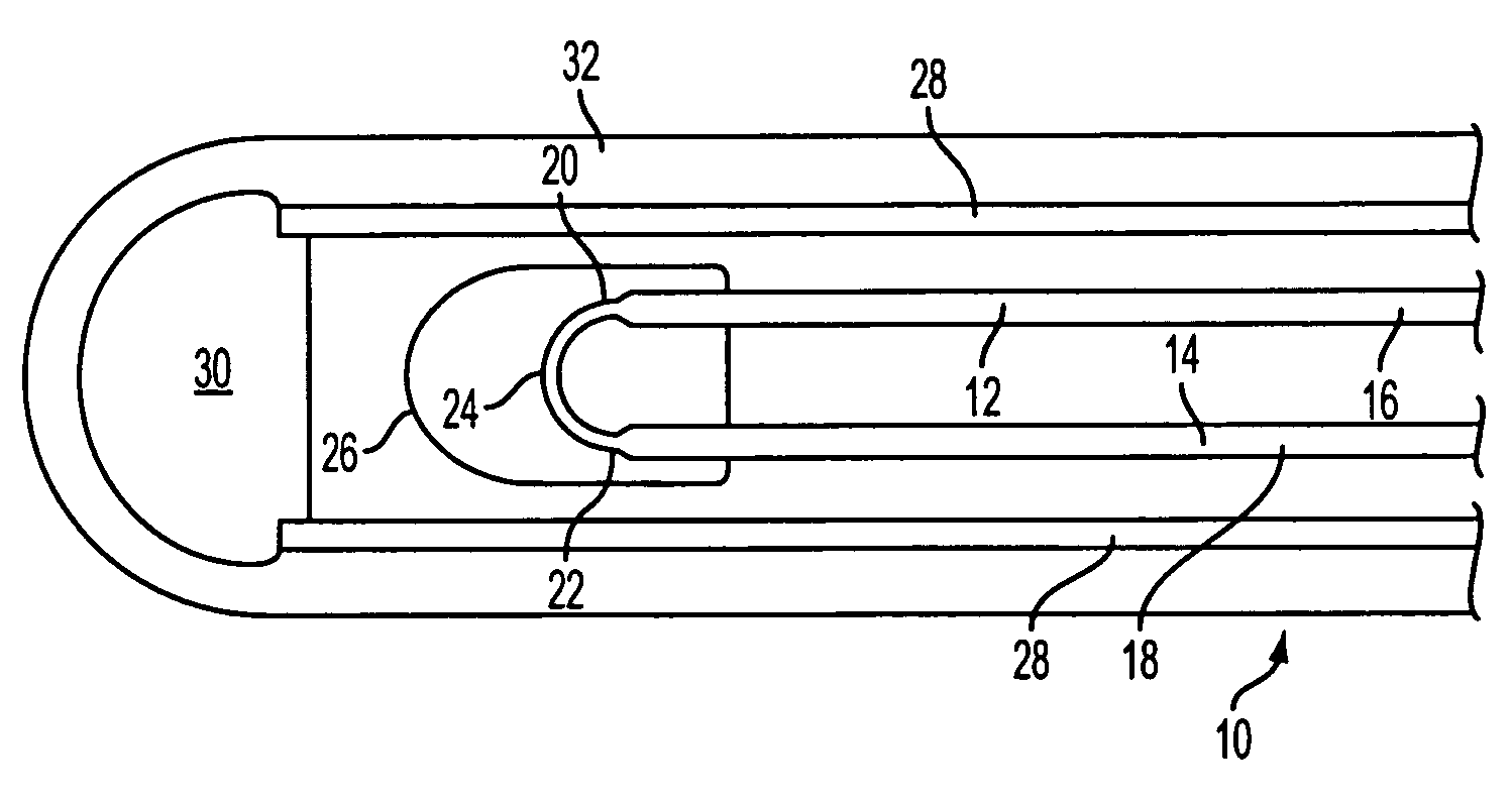
[0024]The present invention provides a fiber optic cable having a miniature bend at one end, thereby permitting connection of the originating and return path within the cable, while minimizing the diameter of the end portion of the cable.

[0025]Referring to FIG. 1, the end portion of a cable 10 is illustrated. The cable 10 includes a pair of optical fibers 12, 14. A miniature bend 24 is attached to the ends 20, 22, connecting the ends 20, 22 together, thereby forming a complete optical path down the fiber 12, through the miniature bend 24, and back through the fiber 14. The miniature bend 24 is surrounded by a protective casing 26, which in some preferred embodiments may be a capillary tube that may be made from glass. The fibers 12, 14, and the protective casing 26, are contained within a tube 28 that may be made from a metal such as stainless steel or from polymeric material. The tube includes a seal 30 at its terminating end. A jacket 32 may surround the seal 30 and tube 28.

[0026]...


PUM


Abstract

A fiber optic cable includes a miniature bend at one end, connecting a pair of optical fibers forming an originating light path with a return light path. The use of the miniature bend to connect to the originating and return light paths results in an end portion of the cable having a sufficiently small diameter to permit the cable to be blown into otherwise inaccessible locations, for example, the control line of an oil well.

Description

CROSS REFERENCE TO RELATED APPLICATIONS[0001]This application is a continuation-in-part of U.S. patent application Ser. No. 10 / 988,197, filed on Nov. 13, 2004, now abandoned.BACKGROUND OF THE INVENTION[0002]1. Field of the Invention[0003]The present invention provides a fiber optic cable for use in temperature measurement in locations inaccessible to humans, for example, the control line of an oil well. More specifically, it provides a double strand fiber optic cable incorporating a miniature bend at the end of the cable, connecting the double strands together.[0004]2. Description of the Related Art[0005]Temperature measurement in locations inaccessible to humans and equipment, for example, the hydraulic control line of an oil well, requires that some type of temperature sensing device be transported to the location where temperature measurement is desired, while overcoming the inaccessibility of the location to humans and equipment. The sensor may take the form of an optical fiber ...

Claims


Application Information

Patent Timeline
11 Sep 2007
Publication
US7269320B2
IPC
G02B6/44
CPC
E21B47/065; G02B6/4415; E21B47/07
Inventors
HERBST, BRIAN