Image transfer device and method for cleaning a part thereof

a technology of image transfer and cleaning method, which is applied in the direction of optics, instruments, electromagnetography/magnetography, etc., can solve the problems of high rejuvenation period, affecting image transfer efficiency and fixing quality, and inconsistent cleaning characteristics, so as to improve the removal of contaminants

Inactive Publication Date: 2007-09-11
OCE TECH
View PDF8 Cites 0 Cited by
  • Summary
  • Abstract
  • Description
  • Claims
  • Application Information

AI Technical Summary

Benefits of technology

[0005]Thus it is an object of the present invention to provide a device and method in which an improved removal of contaminants from the surface of an image transfer member is possible.
[0006]It is still a further object of the present invention to rejuvenate the tacky surface of the cleaning member substantially without affecting the productivity of the image reproduction system.
[0007]It is still a further object of the present invention to rejuvenate the tacky surface of the cleaning member by providing refreshment material and simultaneously removing any excess and / or contaminated tacky surface material therefrom.
[0011]a controllable applicator unit is utilized for providing, in an operative state of the image transfer device, predetermined patterns of a cleaning substance to the surface of the image transfer member in at least some of the non-image areas, the predetermined patterns of cleaning substance provided on the image transfer member being substantially completely transferred to the surface of the cleaning member in the cleaning zone. The present invention is particularly relevant to printers and copiers where, to enable printing on a wide variety of recording media, at least one image transfer device is provided to transfer an image of marking substance from an image forming device to the recording medium. The feature that non-image patterns of cleaning substance are formed in the non-image areas, i.e., the areas between consecutive images coinciding with the areas between consecutive sheets is advantageous as it allows the rejuvenation of the cleaning member surface, quasi continuously. Furthermore, as this takes place in the operative state, i.e. while sheets of recording medium are fed through the transfer zone and hence prints or copies of images are generated, this rejuvenation process does not negatively affect the productivity of the printer or copier.
[0019]In one embodiment of the present invention, the cleaning member is a rotatable cleaning roller having a surface with a plurality of spaced-apart perforations therein for discharging any contaminants and excess cleaning substance assembled on the cleaning roller surface into a cavity in the cleaning roller. For instance, the perforations may be in the form of grooves. An advantage thereof is that the building up on the cleaning member surface of any excess tacky substance possibly mixed with contaminants is prevented. The cleaning roller may be constructed of a metal such as steel or aluminium. The cleaning roller, however, may also be made of other heat-resistant material to the extent comporting with the operating temperature thereof. Such heat-resistant materials may include heat-resistant plastics. Optionally a perforated conformable layer may be provided on the cleaning member core material. In any case, the tacky layer is formed on the cleaning member outer surface.
[0021]In yet a further embodiment of the present invention, the patterns of cleaning substance on the image transfer member are such that the portions of the image transfer member surface, covered by the patterns of cleaning substance, have an area coverage in the range from 1% to 30%. It is observed that by lowering the area coverage of the exposed portions, the transfer efficiency of cleaning substance to the counter member surface in the transfer zone can be effectively reduced.

Problems solved by technology

In such image transfer devices, contaminants, e.g., in the form of residual marking substance material and / or debris originating from the recording medium and / or other impurities may build up on the surface of the image transfer member.
If these contaminants remain on the image transfer member surface, the efficiency of the image transfer and the quality of the fixing, where applicable, may be affected.
The periodic rejuvenation of the tacky surface layer as described is found to lead to inconsistent cleaning characteristics caused by the reduction of the surface tackiness when proceeding in the operative state towards the next rejuvenation period.
However, contrary to the operative state, in the rejuvenation stage no prints or copies are generated and thus a high rejuvenation period is detrimental for the productivity of the image reproduction device.

Method used


Image

  • Image transfer device and method for cleaning a part thereof
  • Image transfer device and method for cleaning a part thereof
  • Image transfer device and method for cleaning a part thereof

Examples


Embodiment Construction

[0027]In relation to the appended drawings, the present invention is described in detail in the sequel. Several embodiments are disclosed. It is apparent however that a person skilled in the art can imagine several other equivalent embodiments or other ways of executing the present invention.

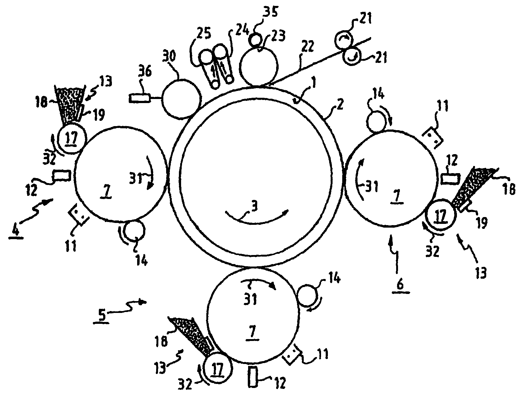
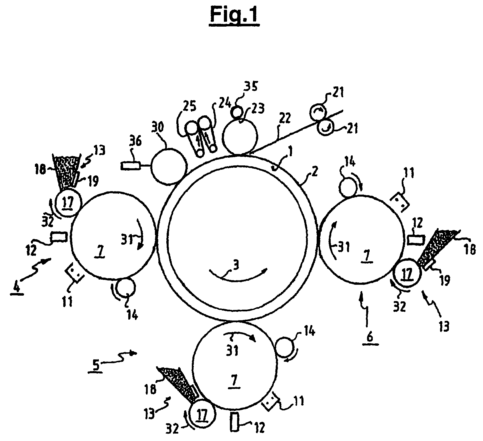
[0028]A printing system capable of printing on sheets of a recording medium is depicted in FIG. 1. The printing system includes an image transfer member, which can be moved cyclically. The image transfer member is an endless member, such as e.g., a drum or a belt. In this case the image transfer member is a cylindrical drum 1, which can be moved in the direction of arrow 3. The image transfer member is constructed of a metal sleeve, e.g., aluminium, with an elastomeric covering 2. Optionally, the image transfer member may be provided with an outer layer of silicone rubber, e.g., by means of a coating. One or more process colors are available on the printing system dependent on whether or not it ...


PUM


Abstract

An image transfer device for a sheet-fed image reproduction system is disclosed in which an improved removal of contaminants from the surface of an image transfer member is possible by using a tacky surface cleaning member contacting the image transfer member surface. The tacky surface of the cleaning member is rejuvenated substantially without affecting the productivity of the image reproduction system by applying predetermined patterns of cleaning substance on the image transfer member surface in the non-image areas, being the part of the inter-image areas coinciding with the inter-sheet areas. Also disclosed is a method for cleaning the image transfer member surface of such image transfer device.

Description

FIELD OF THE INVENTION[0001]The present invention is directed to an image transfer device for transferring images of a marking substance, including ink and toner, from an image transfer member to a recording medium. Furthermore, the present invention is related to a method of removing debris from the surface of the image transfer member of such an image transfer device.BACKGROUND OF THE INVENTION[0002]Image reproduction systems, such as printers and copiers, often include an image transfer device having an image transfer member, usually in the form of a belt or a drum, for receiving on its surface a marking substance, such as toner or ink, in image form and for subsequently transferring these images of marking substance in a transfer zone to a recording medium, such as paper. In an operative state, the image transfer member is urged against a counter member in the transfer zone while the recording medium passes therebetween. The transfer may take place by means of pressure, or heat,...

Claims


Application Information

Patent Timeline
Patent Type & Authority Patents(United States)
IPC IPC(8): G03G15/16
CPCG03G15/161G03G2215/0177G03G2215/1652G03G2215/1657G03G2215/1695G03G15/24
Inventor VAN SAS, LAMBERTUS M. L.
Owner OCE TECH
Why Eureka
Try Eureka