Method and apparatus for memory self testing

a memory and self-testing technology, applied in the field of data processing systems, can solve the problems of increasing the defect density of these memories, and the test methodology adopted by one manufacturer may well not work well for another manufacturer, so as to simplify the interface, different test methodologies, and different designs

Active Publication Date: 2007-09-11
ARM LTD
View PDF7 Cites 19 Cited by
  • Summary
  • Abstract
  • Description
  • Claims
  • Application Information

AI Technical Summary

Benefits of technology

[0011]The invention recognizes that in some circumstances a programmable self-test controller that allows different test methodologies to be performed by varying the address sequencing is desirable. In particular, providing a self-test controller that is programmable in this way enables the design of the self-test controller to be reused by various different manufacturers and yet allows those manufacturers to program the self-test controller to carry out a test methodology they select as best suited to their particular circumstances. Whilst providing a programmable self-test controller as opposed to one that can carry out merely one fixed test methodology does slightly increase the size and complexity of the self-test controller in a manner that would generally be regarded as disadvantageous, in practice this disadvantage is more than outweighed by the ability to reuse the self-test controller design to cope with the different test requirements of different manufacturers or the different test requirements that may arise for a single manufacturer as they evolve their own fabrication processes.
[0014]It will be appreciated that the memory addresses that are produced by the self-test controller could take a variety of forms and be mapped to the memory locations in different ways. However, many types of memory defects are associated with the physical location of a memory location in itself or relative to other memory locations and accordingly memory addresses that directly represent row and column addresses that give a physical position for the memory location are particularly well suited for generation by the self-test controller since the sequences of memory addresses that are useful in testing will generally be more easily formed when the memory addresses are represented in this way.
[0031]A further complication with the present technique is that different memories may require different signal values and timings in order to drive them. The desire to provide a generic self-test controller of a comparatively simple design makes it impractical to deal with such differences within the self-test controller. Accordingly, preferred embodiments of the invention include an interface circuit that performs any necessary signal value and timing adjustments required between the self-test controller and the memory under test. Concentrating the circuit elements required to connect to a particular memory together within an intervening interface circuit allows the design of the self-test controller to remain generic and relatively compact.
[0033]It will be appreciated that many modern integrated circuits often include multiple different memories. These different memories may have quite different designs and require different test methodologies. The programmable nature of the self-test controller allows this single circuit to test such different memories in a way best suited to the particular memory concerned. The self-test instructions may also specify the way in which any detected errors are to be reported. This is an advantageous feature that allows the error reporting to be tuned to a particular manufacturer's requirement or even to reflect different test environments, such as design debugging compared with manufacturing test.
[0036]In order to reduce the connection overhead associated with the self-test controller preferred embodiments serially load the self-test instructions into the self-test controller.

Problems solved by technology

As memory sizes increase, the proportion of the die being taken up by the memory is also increasing and, furthermore, the high transistor density within memory means that the defect density of these memories is becoming increasingly significant.
The test methodology adopted by one manufacturer may well not work well for another manufacturer.

Method used


Image

  • Method and apparatus for memory self testing
  • Method and apparatus for memory self testing
  • Method and apparatus for memory self testing

Examples


Embodiment Construction

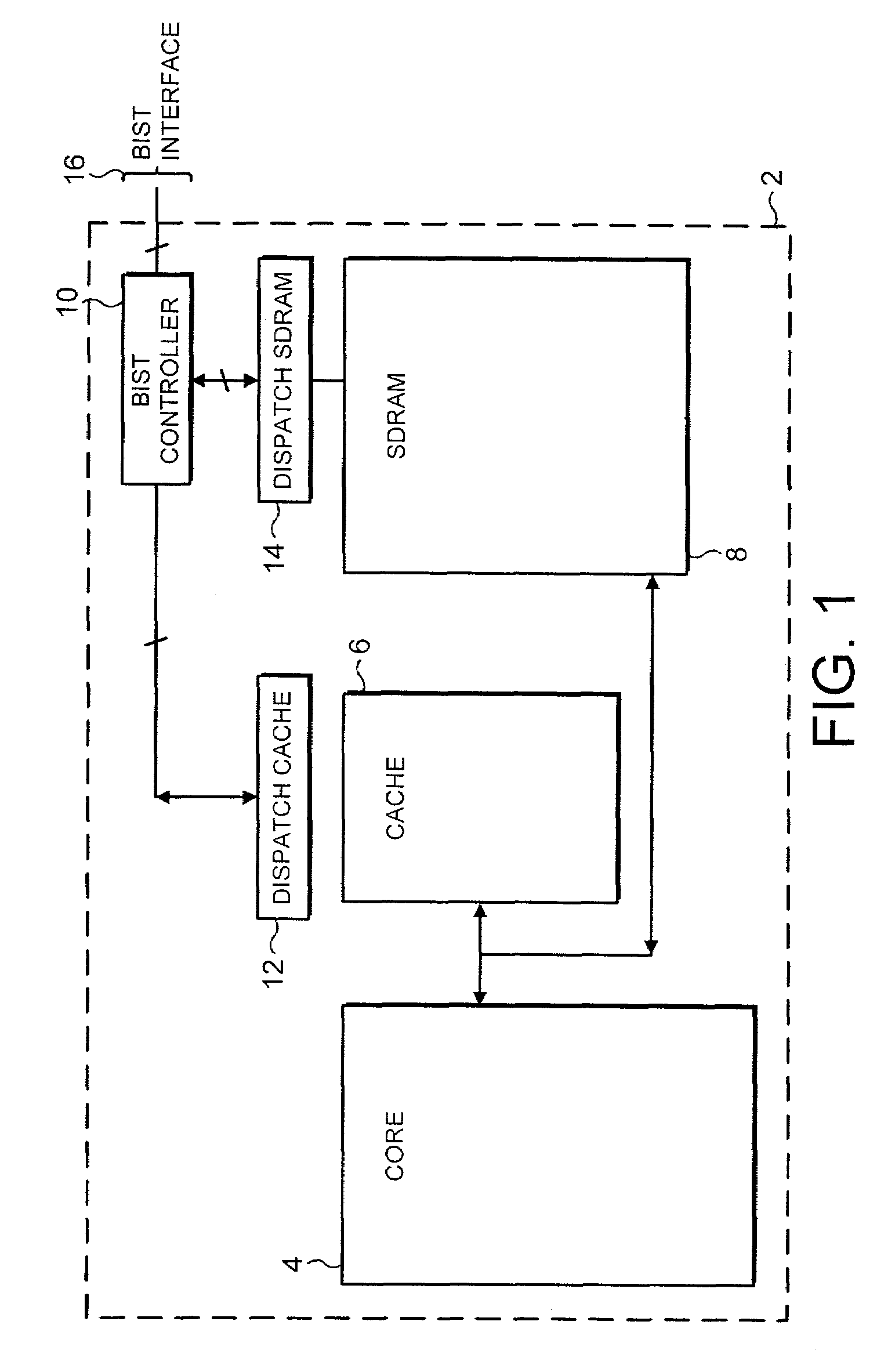
[0049]FIG. 1 shows an integrated circuit 2 incorporating a processor core 4, a cache memory 6 and an RAM memory 8 (in this example SDRAM). It will be appreciated that such an integrated circuit 2 will typically include many more circuit elements, but these have been omitted from this drawing for the sake of simplicity and clarity.

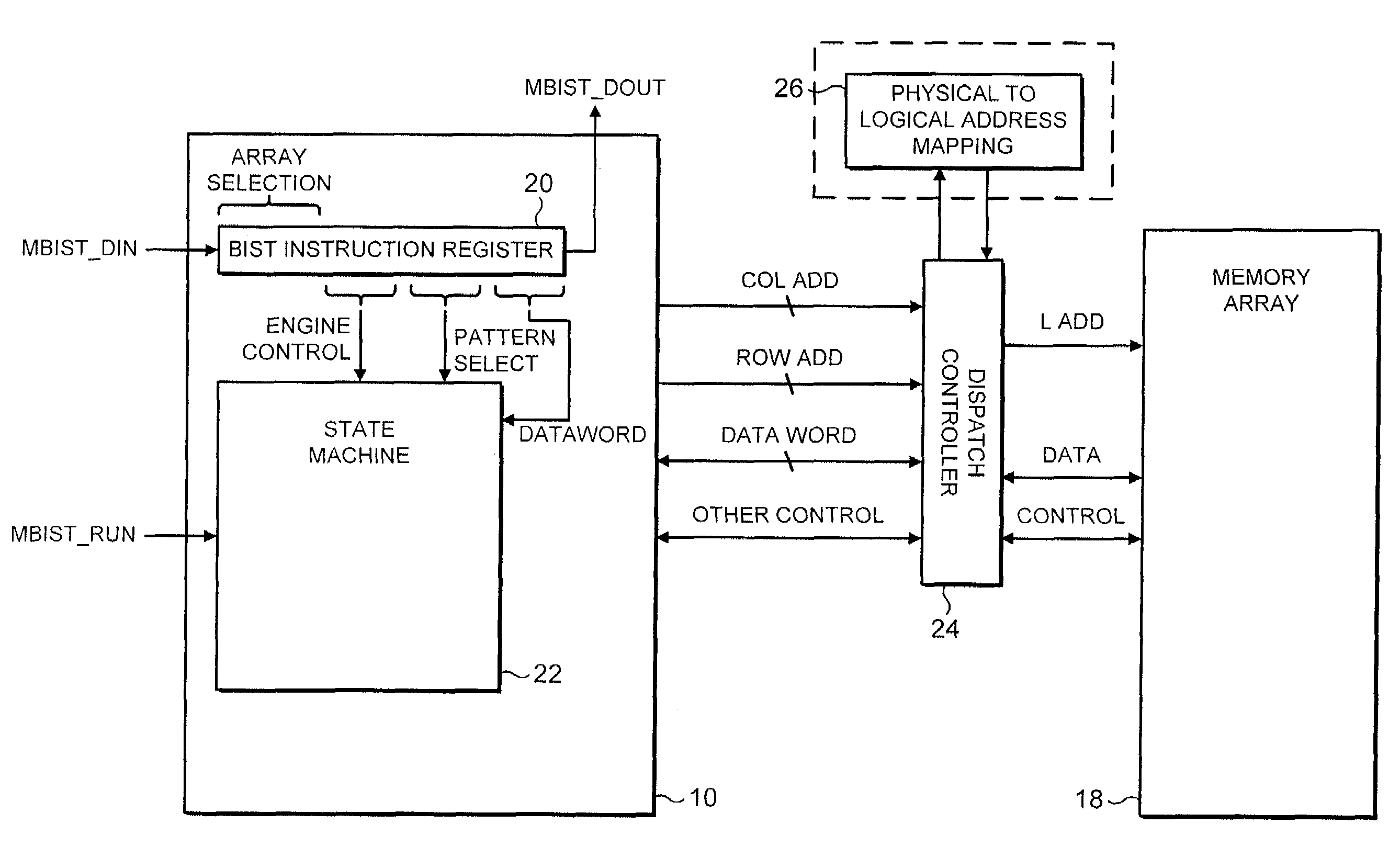
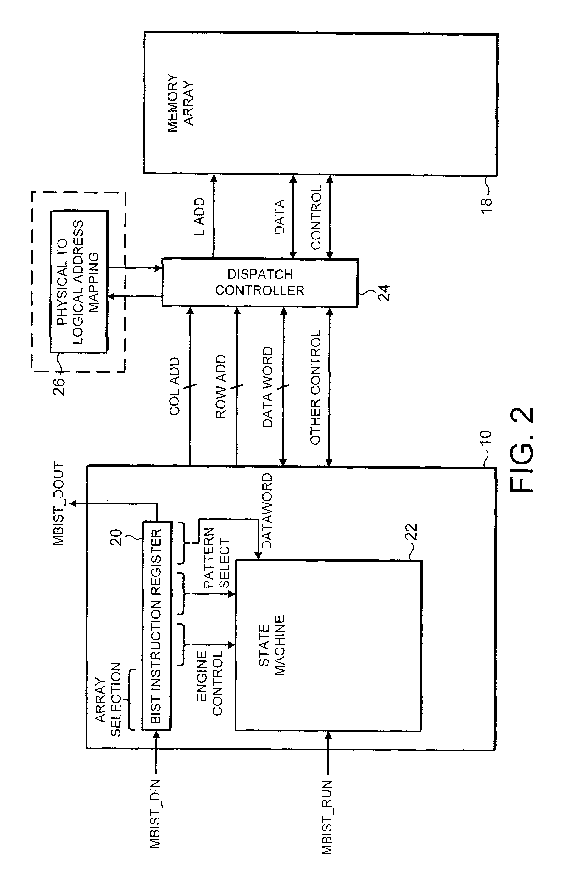
[0050]A self-test controller 10 is provided on the integrated circuit 2 and communicates with each of the cache memory 6 and the SDRAM memory 8 by a respective dispatch circuit 12, 14. These dispatch circuits act as interface circuits between the self-test controller 10 and the respective memories. Thus, generic memory test driving signals produced by the self-test controller can be re-mapped to logical addresses and adjusted in value and timing to the requirements of the different memories without a need to change the fundamental design of the self-test controller 10.

[0051]It will also be seen that the self-test controller 10 includes a self-test interface...


PUM


Abstract

A self-test controller 10 is responsive to scanned in self-test instructions to carry out test operations including generating a sequence of memory addresses that is specified by the self-test instruction. Combining multiple such self-test instructions allows a custom test methodology to be built up by a user using a generic self-test controller 10.

Description

BACKGROUND OF THE INVENTION[0001]1. Field of the Invention[0002]This invention relates to the field of data processing systems. More particularly, this invention relates to the self-testing of memories within data processing systems to detect memory defects.[0003]2. Description of the Prior Art[0004]It is known to provide data processing systems incorporating memories with self-testing mechanisms, sometimes termed built-in self-test (BIST), such that when the memory circuits have been fabricated they may conduct a self-test or series of self-tests to determine if there are any memory defects present that would indicate that the circuit should be rejected. It is important that memory circuits should be highly reliable and that defective circuits should be effectively identified. As memory sizes increase, the proportion of the die being taken up by the memory is also increasing and, furthermore, the high transistor density within memory means that the defect density of these memories ...

Claims


Application Information

Patent Timeline
Patent Type & Authority Patents(United States)
IPC IPC(8): G11C29/00G01R31/28G06F12/16G06F15/78G11C29/02G11C29/16
CPCG11C29/16
Inventor SLOBODNIK, RICHARDHILL, STEPHEN JOHNWILLIAMS, GERARD RICHARD
Owner ARM LTD
Why Eureka
Try Eureka