Diamond window component for a laser tool

a laser tool and component technology, applied in the direction of light therapy, telescopics, rigid pipes, etc., can solve the problems of exacerbated problem, window debonding from tubular, small end tip of laser tool, etc., to achieve small end tip size, rapid temperature increase, and little energy

Active Publication Date: 2015-05-26
ELEMENT SIX TECH LTD
View PDF19 Cites 0 Cited by
  • Summary
  • Abstract
  • Description
  • Claims
  • Application Information

AI Technical Summary

Benefits of technology

[0010]One way to alleviate some of the aforementioned problems is to provide an efficient cooling system to prevent the end tip from heating too rapidly or becoming too hot. However, incorporating an efficient cooling system can increase the size and complexity of the device which is not desirable.
[0034]The aperture is advantageously elongate having a longest dimension extending along a length of the tubular body. This will allow for slight variations in the longitudinal position of an optical fibre disposed within the tubular body. An elongate diamond window may be provided for covering such an elongate aperture. As such, slight variations in attachment of the component to an optical fibre are tolerated. For example, the aperture may have a length in the range 1.0 mm to 8.0 mm, 1.0 mm to 5.0 mm, or 1.0 mm to 3 mm. Furthermore, the aperture may have a width in the range 0.5 mm to 5.0 mm, 0.5 mm to 3.0 mm, or 0.5 mm to 2.0 mm.
[0035]The overlap between the diamond window and a side wall of the tubular body around the aperture may be 0.2 mm to 1.0 mm, 0.3 mm to 0.8 mm, 0.35 mm to 0.6 mm, or more preferably 0.4 mm to 0.5 mm. The relative size of the diamond window and the aperture is selected to achieve a reliable bond between the diamond window and the tubular body around the aperture and to provide an optimal thermal contact between the diamond window and the tubular body.
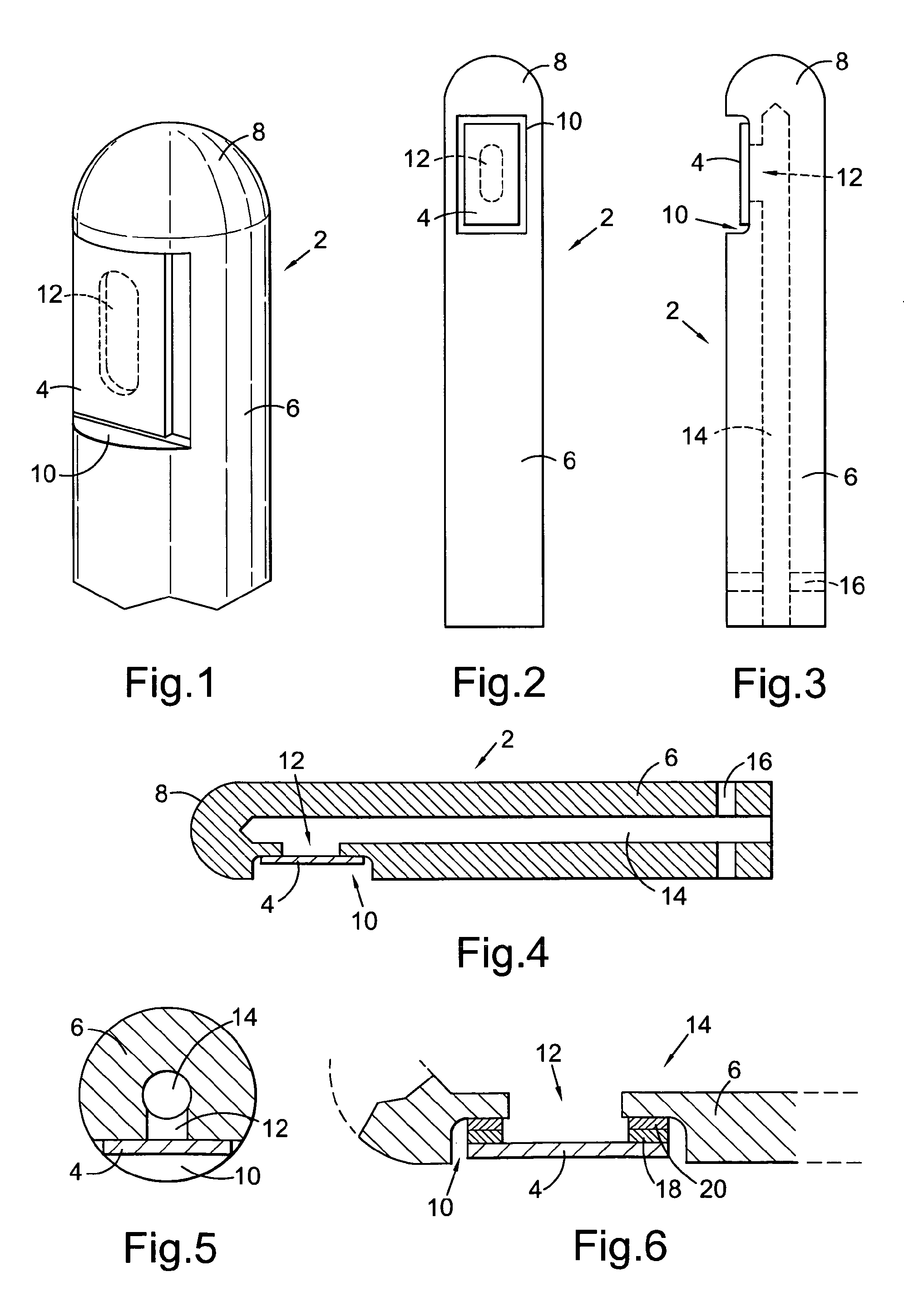
[0036]One further problem which the present inventors have identified is that the diamond window can have very sharp edges causing lacerations during medical applications. As such, it has been found to be advantageous to position the aperture in a recess in the side wall of the tubular body and locate the diamond window in the recess across the aperture, the diamond window having an area less than an area of the recess and greater than an area of the aperture. This arrangement ensures that the diamond window extends across the entire aperture while being wholly located within the recess such that no sharp edges protrude out from the tubular body. In order to further negate the possibility of a diamond edge cutting into a patient, one or more edges of the diamond window can be chamfered such that they are flush to a wall of the tubular body.
[0037]The diamond window is preferably bonded to the tubular body around the aperture to form a seal all around the aperture. This will prevent fluid or other debris entering the tubular member and fouling the optical fibre.

Problems solved by technology

It has been found that the small end tip of the laser tool becomes very hot during operation.
If the stress becomes too large, then the joint fails and the window de-bonds from the tubular body.
Repeated heating and cooling in use can exacerbate this problem.
Furthermore, autoclaving the apparatus in order to sterilize the apparatus between uses can also exacerbate this problem.
A similar problem can also occur during manufacture of the component if any thermal processing steps are utilized.
For example, if the diamond window is welded or brazed to the tubular body, strain generated during cooling of the component due to a mismatch in thermal expansion coefficient can cause the diamond window to de-bond.
However, incorporating an efficient cooling system can increase the size and complexity of the device which is not desirable.
However, flexible joints such as polymer adhesives are susceptible to melting and burning during use and / or are not suitable for autoclaving.

Method used


Image

  • Diamond window component for a laser tool
  • Diamond window component for a laser tool

Examples


Embodiment Construction

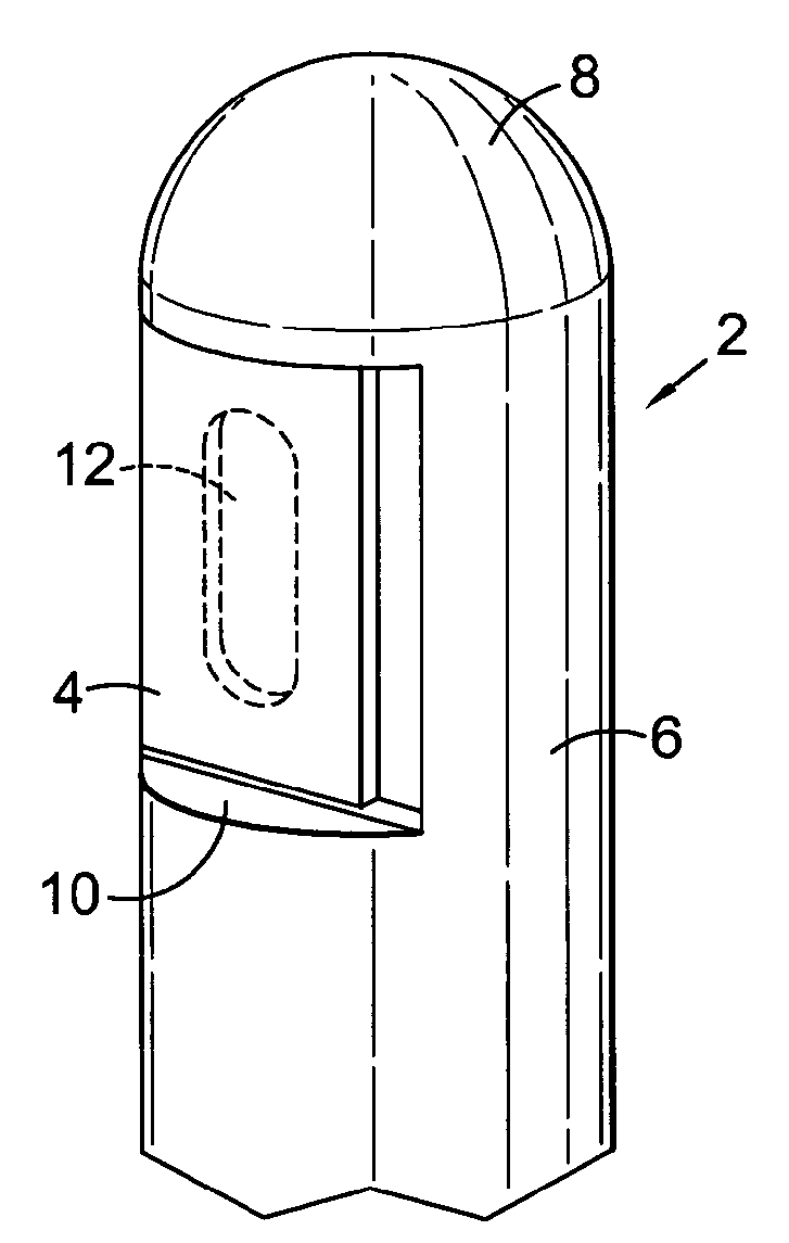
[0045]FIGS. 1 to 6 show various views of a diamond window component for a laser tool such as a medical probe for treating Benign Prostatic Hypertrophy. The component comprises a tubular body 2 and a diamond window 4. The tubular body 4 comprises an elongate hollow tube 6 and an end cap 8. The diamond window 4 is disposed in a recess 10 in a side wall of the elongate hollow tube 6. An aperture 12 is disposed in the side wall of the elongate hollow tube 6 under the diamond window 4 which allows laser light to pass from an interior channel 14 in the elongate hollow tube 6 out through the diamond window 4.

[0046]An end of the tubular body 2 opposite the end cap 8 is configured for attachment to an end of an optical fibre to transmit laser light down the interior channel 14. In the illustrated embodiment, an optical fibre can be inserted into the interior channel 14 and secured with screws 16 as shown in FIGS. 3 and 4. The optical fibre may be of the side-firing type. Alternatively, if an...


PUM

PropertyMeasurementUnit
absorption coefficientaaaaaaaaaa
operating wavelengthaaaaaaaaaa

Abstract

A component for a laser tool, the component comprising: a tubular body defining an internal channel and an aperture; and a window disposed across the aperture and bonded to the tubular body around the aperture, wherein the window is diamond, and wherein the tubular body comprises a material having a coefficient of linear thermal expansion α of 14×10−6 K−1 or less at 20° C. and a thermal conductivity of 60 Wm−1K−1 or more at 20° C.

Description

FIELD OF INVENTION[0001]The present invention relates to a diamond window component for a laser tool. Certain embodiments relate to a laser medical probe.BACKGROUND OF INVENTION[0002]The use of diamond as a window material in a laser tool is known. Diamond is useful as a window material as it has low absorption for infrared wavelengths in order to transmit a high power laser beam.[0003]One such use is in a medical laser probe comprising an optical fibre for transmitting a laser beam to a point within the body where a surgical procedure is to be performed. For example, JP 9028715, JP 5095962, U.S. Pat. No. 4,170,997 and U.S. Pat. No. 6,104,853 disclose the use of diamond as a window material disposed in the end of a medical laser probe. Medical laser probes can be used to perform surgical procedures including, for example, cutting and / or ablating tissue. Using a laser rather than a standard cutting tool can be advantageous in that the tissue is cauterized reducing blood loss and incr...

Claims


Application Information

Patent Timeline
Patent Type & Authority Patents(United States)
IPC IPC(8): B32B1/00A61N5/06A61B18/00A61B18/20A61B18/22A61B18/24G02B23/24
CPCA61B18/201G02B23/2492Y10T428/131Y10T428/13Y10T428/12361A61B18/22A61B18/24A61B2018/00095A61B2018/2255A61M25/0043G02B23/2476H01L23/3732H01S3/0305H01S3/034A61B2018/2222
Inventor DEWIT, HENDRIKUS GERARDUS MARIAPELS, GERRIT JAN
Owner ELEMENT SIX TECH LTD
Why Eureka
Try Eureka