Nebulizer apparatus and method

a nebulizer and airflow technology, applied in the field of nebulizer apparatus and method, can solve the problems of aerosol waste, aerosol may be lost to condensation on the nebulizer or mouthpiece, aerosol may be lost to the condensation of the nebulizer or the airflow may be difficult to quantify, etc., to achieve a larger chamber area, reduce the impact of the aerosol against the chamber wall, and improve the distribution of aerosol particle siz

Active Publication Date: 2007-09-18
TRUDELL MEDICAL INT INC
View PDF108 Cites 59 Cited by
  • Summary
  • Abstract
  • Description
  • Claims
  • Application Information

AI Technical Summary

Benefits of technology

[0009]According to other aspects of the invention, a nebulizer may be constructed with an aerosolization chamber having a first diameter in a plane substantially co-planar with an aerosolization plane in which the majority of aerosol is generated within the chamber, and a second diameter in a plane other than the aerosolization plane, where the first diameter is greater than the second diameter. The impaction of the aerosol against the chamber walls may be reduced, and aerosol particle size distribution improved, with a larger chamber area where the aerosol is generated. In alternative embodiments, the chamber may have curved or angled walls tapering in at the bottom of the chamber, or at both the top and bottom of the chamber.

Problems solved by technology

Continuous nebulization may result in a waste of aerosol, such as to the atmosphere, during a patient's exhalation or during a delay between inhalation and exhalation.
The amount of wasted aerosol may be difficult to quantify and some of the aerosol may be lost to condensation on the nebulizer or mouthpiece, or to evaporation, during periods of non-inhalation.
Nebulizers implementing a timed or non-continuous nebulization may adversely affect particle size and density as the nebulization is turned on and off.
The greater the flow rate, air leaks and friction, the greater the inhalation effort required in order to actuate the device.
Most nebulizer designs have difficulty delivering all of the medication that is placed in the nebulizer to the patient.
The inefficiency in delivering the medication may stem from some of the medication sticking to the chamber walls of the nebulizer, structural issues in the nebulizer that prevent medication from reaching the desired destination, and other reasons.
Failure to use all of the medication adds to the cost of aerosol delivery and can create uncertainty concerning the actual dosage of medication delivered to a patient.

Method used


Image

  • Nebulizer apparatus and method
  • Nebulizer apparatus and method
  • Nebulizer apparatus and method

Examples


Embodiment Construction

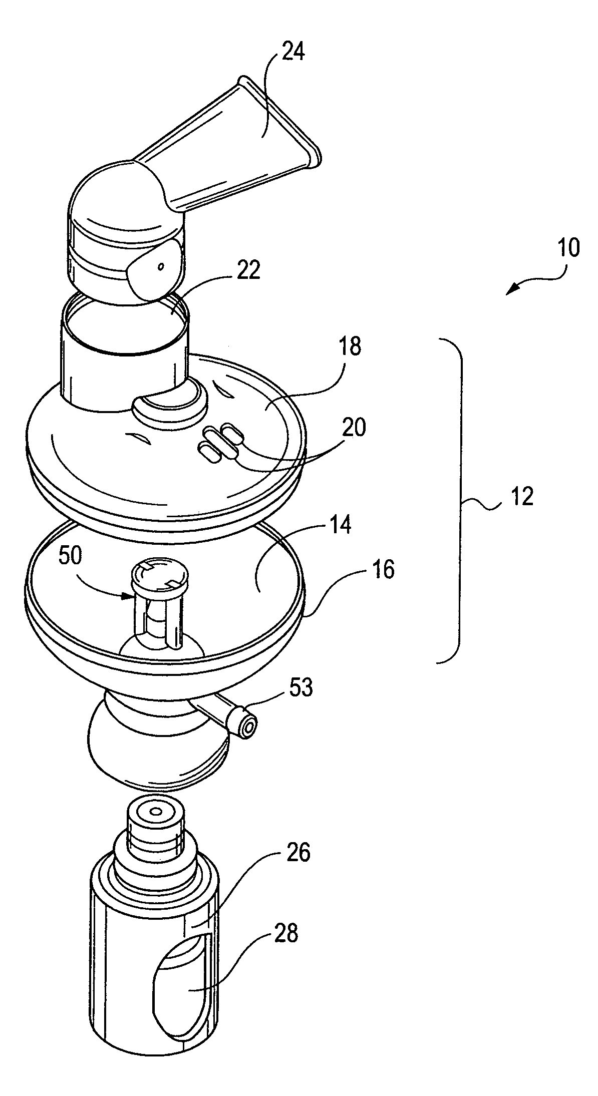
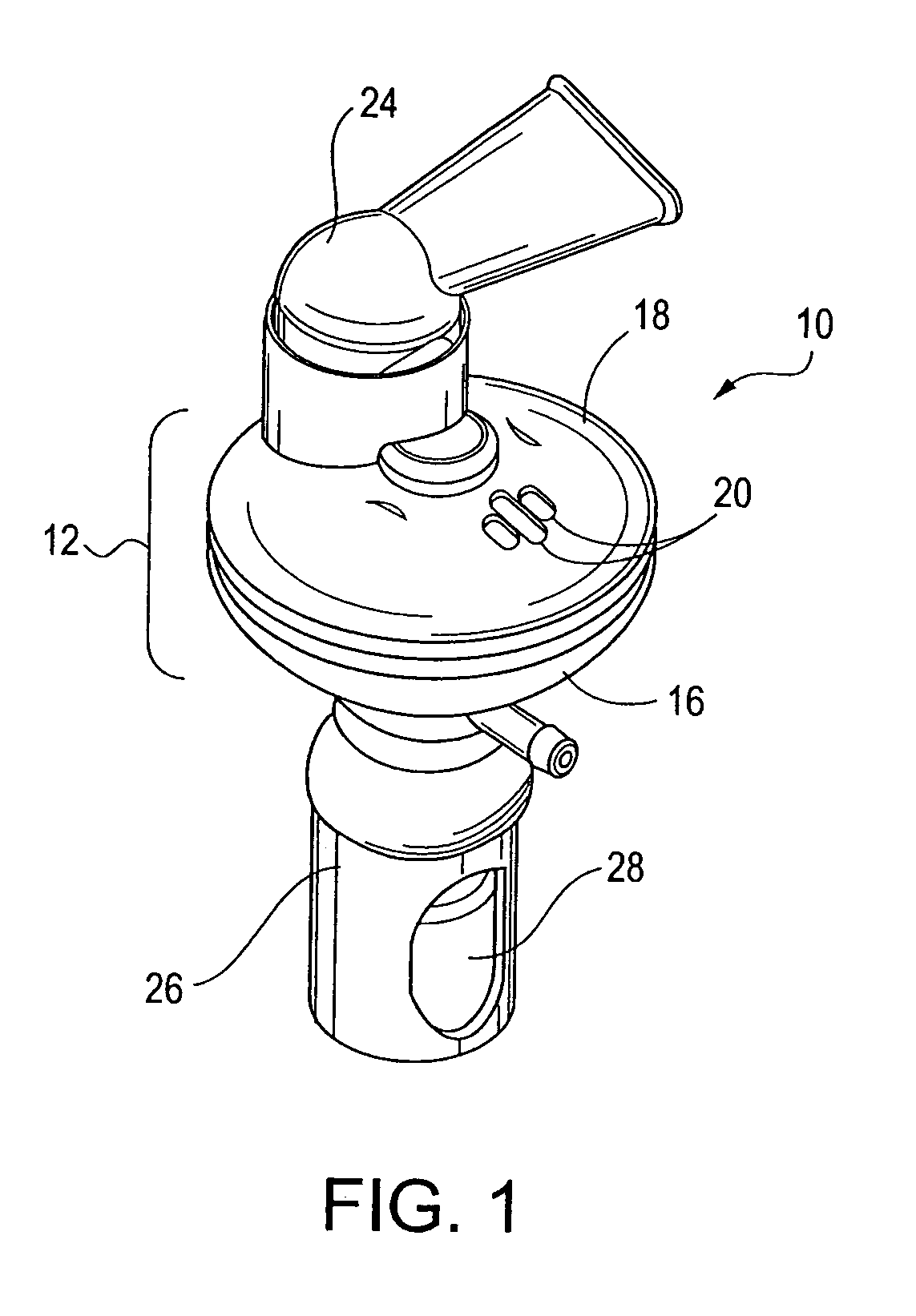
[0045]An embodiment of a nebulizer 10 for nebulizing a fluid drawn from a vial connected to the nebulizer is shown in FIGS. 1-2. As used in this specification, the term “fluid” includes, without limitation, a fluid comprising a medicine, whether in the form of an emulsion, suspension or solution that can be nebulized into an aerosol.

[0046]The nebulizer 10 includes a housing 12 consisting of a base 16 that is removably attachable with a cover 18. The interior of the base and cover is hollow and defines a chamber 14 that is suited to receive an aerosol. The chamber 14 may be any number of shapes and preferably is angled or curved inward towards its bottom so that any aerosol that impacts the interior wall of the chamber 14 will condense and be drawn toward the bottom of the chamber 14. An air inlet 20, comprised of one or more openings in the cover 18, permits air to be drawn into the chamber 14. An air outlet 22 extends through the cover 18. In one embodiment, the air outlet 22 is of...


PUM


Abstract

A nebulizer for efficiently and reliably delivering aerosolized fluid to an inhaling patient is disclosed. The nebulizer, in one embodiment, includes a fluid channel air inlet and fluid channel air inlet valve responsive to either a manual force external of the nebulizer, or a patient's breathing, to begin the nebulization process. The nebulizer also includes a fluid return channel to a fluid source, such as a removable vial, containing fluid to be aerosolized.

Description

CROSS-REFERENCE TO RELATED APPLICATIONS[0001]This application claims the benefit of U.S. Provisional Application Ser. No. 60 / 494,892, filed Aug. 13, 2003, pending, the entirety of which is incorporated herein by reference.FIELD OF THE INVENTION[0002]The present invention relates to an apparatus and method for generating an aerosol for delivery to a patient. More particularly, the present invention relates to a nebulizer configured to remove a fluid from a source of fluid and generate an aerosol in coordination with a patient's breathing. The present invention is also well suited for continuously generating an aerosol independent of a patient's breathing.BACKGROUND[0003]Medical nebulizers that nebulize a fluid into an aerosol for inhalation by a patient are well-known devices commonly used for the treatment of certain conditions and diseases. Nebulizers have applications for conscious, spontaneously breathing patients and for controlled, ventilated patients. As used in this specifica...

Claims


Application Information

Patent Timeline
Patent Type & Authority Patents(United States)
IPC IPC(8): A61M11/00A61M11/06
CPCA61M11/06A61M11/002A61M2206/14
Inventor GRYCHOWSKI, JERRYFOLEY, MARTIN P.NUTTALL, MICHAEL
Owner TRUDELL MEDICAL INT INC
Why Eureka
Try Eureka