Data encoding mark for placement in a compact area and an object carrying the data encoding mark

a data encoder and compact technology, applied in the field of data encoders for placement in compact areas, can solve the problems of limiting the space in which bar codes can fit, affecting the recognition speed of objects, so as to reduce the handling of objects and accelerate the recognition speed

Inactive Publication Date: 2007-09-18
KOZIOL JEFFREY E
View PDF30 Cites 37 Cited by
  • Summary
  • Abstract
  • Description
  • Claims
  • Application Information

AI Technical Summary

Benefits of technology

[0014]Another object of the invention is to provide a machine-readable code that may be read from any perspective without concern for orientation or alignment, thereby, allowing the object on which the mark is placed, affixed or located to be in any orientation with respect to the encoding mark reader. The advantages of this capability allows for reduced handling operations of the object, faster recognition times because the object does not have to be manipulated for the encoding mark to be read, and simplicity of use of the entire encoding / decoding system.
[0015]Another object of the invention is to provide a code that may be placed within a small compact area without suffering from defects in detection or decoding.

Problems solved by technology

Another problem is placing a bar code in a small compact space.
Since typical bar codes are horizontal, the amount of space in which they can fit is limited by the amount of horizontal space available on the object to be marked.
Furthermore, a typically bar code can only encode approximately ten digits per inch.
U.S. Pat. No. 3,643,068 to Mohan et al. also discloses a circular code for representing a packed binary coded decimal, but the amount of data is limited because each circular band is crossed by a radial wedge that separates the circular bands into regions of equal size.

Method used


Image

  • Data encoding mark for placement in a compact area and an object carrying the data encoding mark
  • Data encoding mark for placement in a compact area and an object carrying the data encoding mark
  • Data encoding mark for placement in a compact area and an object carrying the data encoding mark

Examples


Embodiment Construction

The Encoding Mark

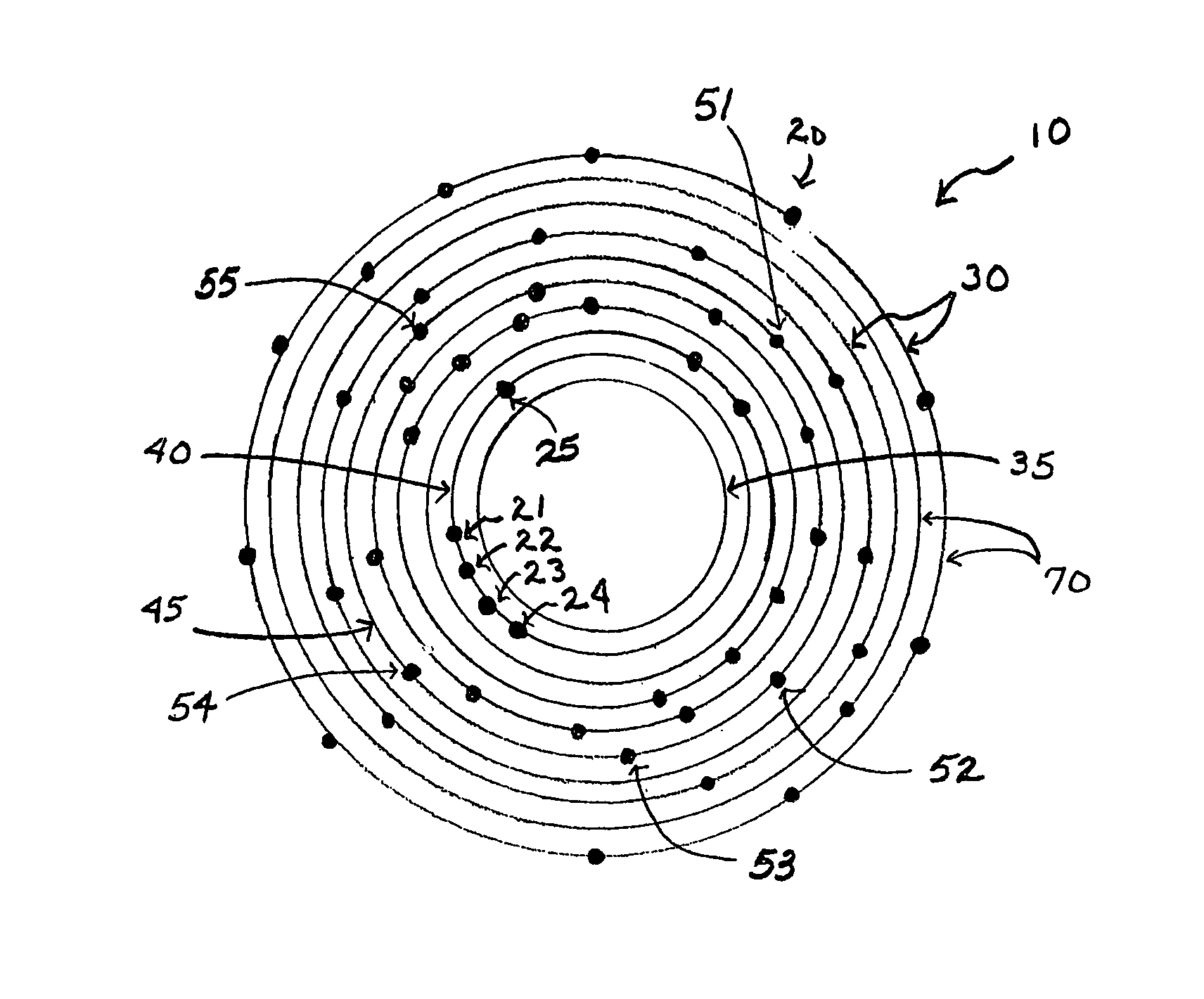
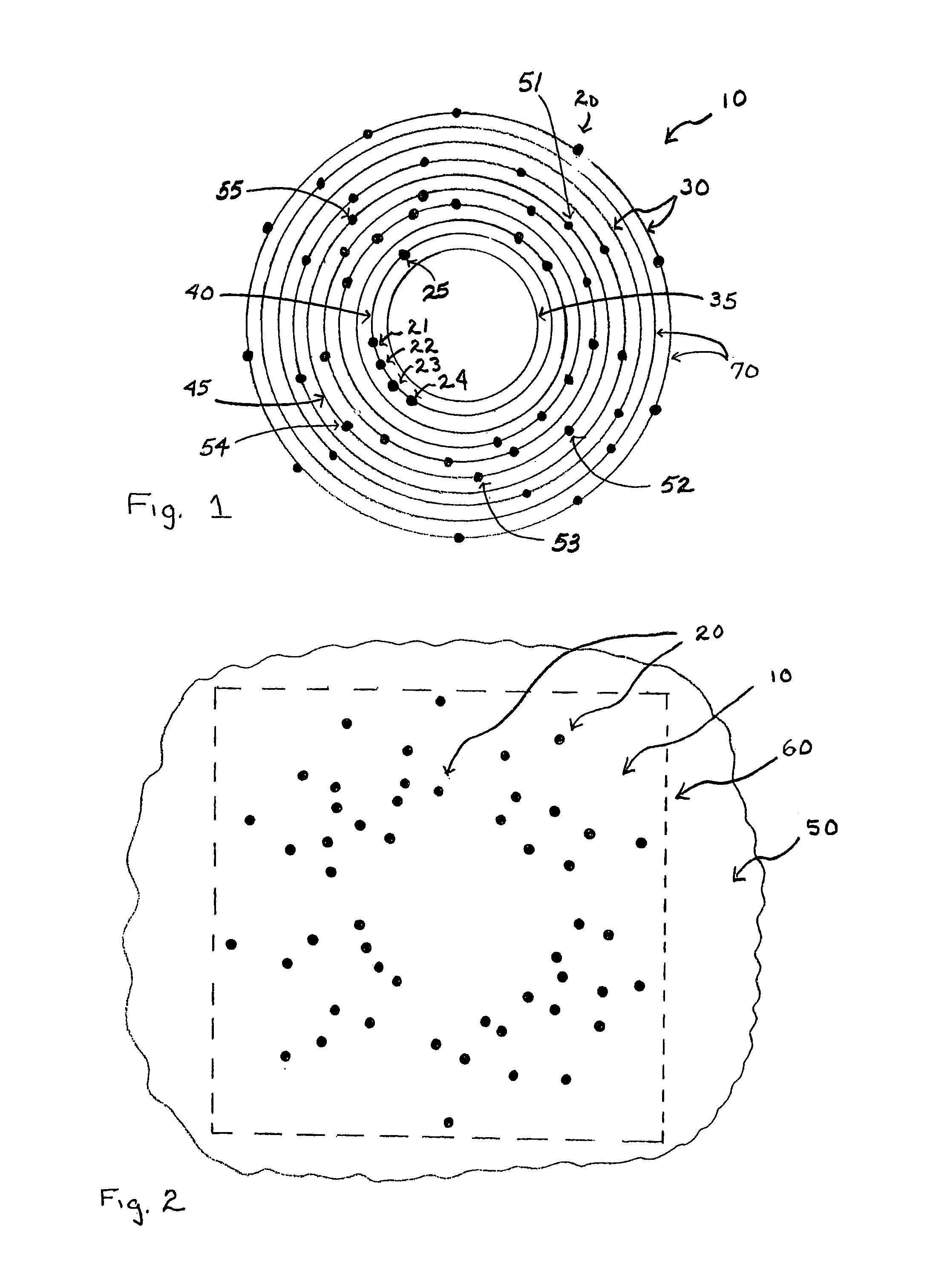
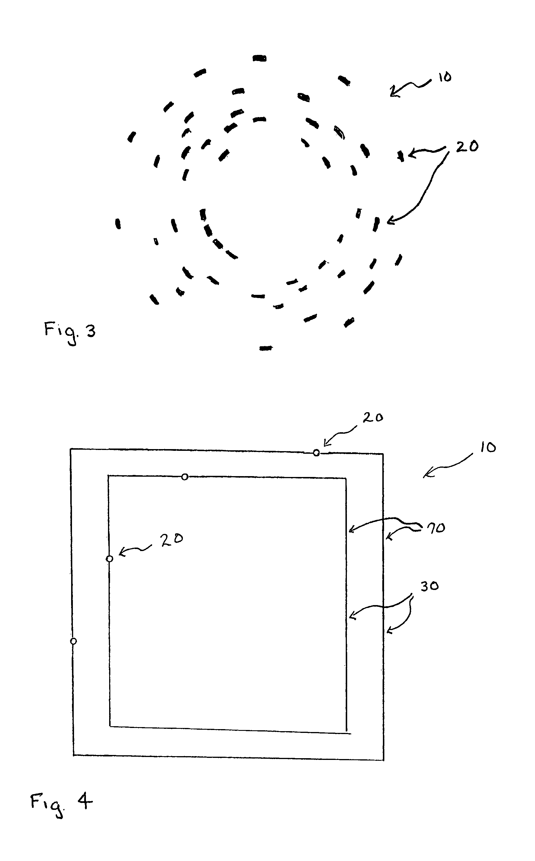
[0028]As seen in FIGS. 1-4, the machine-readable encoding mark 10 in accordance with the present invention includes a series of substantially concentric shapes 30 and distinctive markings 20, placed on the perimeter 70 of concentric shapes 30. Concentric shapes means that the shapes have a common center. In a preferred embodiment, dots (filled-in circles) are placed substantially on the perimeter of concentric circles. Preferably, the distinctive markings may be of a color that provides sufficient contrast to the surface of the object, so that any reading device may obtain a distinct image of the encoding mark. It is conceivable that the object may be marked with concentric shapes which also may be of any color including matching the distinctive markings. Preferably, the concentric shapes will also have a high contrast to the surface of the object and the distinctive marks. The size of the distinctive marks is only limited by the device placing the mark and the opti...


PUM


Abstract

The encoding mark uses a series of shapes as a guide, each of shape capable of being encoded with a finite number, including zero, of distinctive markings. The encoding of a predetermined identifier is performed by placing a predetermined number of distinctive markings substantially on the perimeter of at least one of the shapes in any spatial orientation with respect to each other on the series of shapes. The predetermined number of distinctive markings and the specific one of the shapes on which the distinctive mark is placed corresponds to a predetermined identifier. Since the shapes may only be a guide, they are not required to appear on the object marked with the encoding mark.

Description

FIELD OF THE INVENTION[0001]The present invention relates to marking objects with encoded data. More particularly, the invention is directed towards a machine-readable background marking placeable in a small compact area to facilitate uniquely identifying objects irregardless of the mark orientation.BACKGROUND OF THE INVENTION[0002]In many machine-readable data encoding methods (bar code, MaxiCode, etc.), it is necessary for the encoded mark to be in the proper orientation or alignment to be accurately decoded. A variety of methods have been patented that attempt to solve this problem. U.S. Pat. No. 3,585,366 to Kern teaches a circular code that requires the user to place the point of a reading device in the center of the circular code. Alignment is assured by the point of the reading device protruding into a hole or dimple in the surface on which the circular code is affixed. Kern also uses bar-shaped indicia to represent the data encoded in the circular code.[0003]U.S. Pat. No. 3,...

Claims


Application Information

Patent Timeline
Patent Type & Authority Patents(United States)
IPC IPC(8): G06K19/06
CPCG06K19/06037
Inventor KOZIOL, JEFFREY E.
Owner KOZIOL JEFFREY E
Why Eureka
Try Eureka