Backlighting for electrical cover plates

a technology for electrical covers and backlighting, which is applied in the direction of casings/cabinets/drawers, casings/cabinets/drawers, instruments, etc., can solve the problems of not being able to determine whether, and people may not be able to visually identify at the power outl

Inactive Publication Date: 2007-09-18
HEATHER LEIGH BRANTLEY TRUSTEE FOR THE BRANTLEY CHILDREN TRUST A TEXAS TRUST
View PDF9 Cites 51 Cited by
  • Summary
  • Abstract
  • Description
  • Claims
  • Application Information

AI Technical Summary

Benefits of technology

[0005]A backlit cover plate for use with an electrical supply addresses these and other needs in the art. The backlit cover plate comprises a plate, the plate including a window therein, and backlighting powered by the electrical supply, the backlighting disposed to be mounted on the plate so as to shine through the window. The backlit cover plate may optionally further comprise a switch on the electrical supply, the switch having an operating mechanism to alternatively connect or interrupt the electrical supply, the plate further comprising an opening, the operating mechanism of the switch receivable in the opening, the backlighting connected to the power supply so as to be energized when the switch interrupts the power supply. In addition, the backlit cover plate may optionally further comprise a label, the label including a translucent background and an opaque foreground comprising data to be communicated, the label disposed to be mounted so that the backlighting shines through the window and the label. It will be seen that a technical advantage of the invention includes backlighting a portion of a cover plate, addressing some of the problems encountered by conventional cover plates. For instance, embodiments of the invention allow visual monitoring of an electrical circuit at a light switch or power outlet.
[0006]Further technical advantages include visual identification of light switches and power outlets, which, especially in conjunction with a backlit label, assists an individual in not turning on the wrong light or plugging an appliance into the wrong power outlet by mistake. When in use with a power outlet, a further technical advantage includes freeing up all available outlets of a power outlet, without using up one outlet to illuminate the cover plate itself. The invention also allows an individual to use the proper light switch or power outlet when lighting is poor, which enhances convenience and improves safety to the individual. The invention further allows different colors to be used for the backlighting, which allows an individual to use the invention for aesthetics or color coding. Although the invention is conveniently embodied on a cover plate for use with standard household AC electrical supply, the invention is not limited. In this regard, it will be appreciated that other embodiments are possible for any type of power supply in any environment. Note also that the invention is not limited to AC embodiments. Although the invention is described herein with respect to embodiments using electroluminescence for backlighting powered by AC supply, it will be seen that the principles of the invention apply with equivalent enabling effect to embodiments relying on DC power supply. The foregoing has outlined the features and technical advantages of the present invention in order that the

Problems solved by technology

Further, if a light is not working when the controlling light switch is in the on position, a problem is presented because a person entering a darkened space cannot visually identify whether the problem is the light bulb or the circuit connected to the light switch.
If the breaker has not interrupted the flow of electricity to the light switch, one may not be able to determine whether the source of the problem is the light switch or the light without further inquiry.
If the electrical device is not operating when turned on, a problem is presented because one cannot visually identify whether the electrical device is malfunctioning or the electrical circuit at the power outlet is not providing electricity.
In addition, a person may not be able to visually identify at the power outlet which electrical device is plugged into a particular outlet.

Method used


Image

  • Backlighting for electrical cover plates
  • Backlighting for electrical cover plates
  • Backlighting for electrical cover plates

Examples


Embodiment Construction

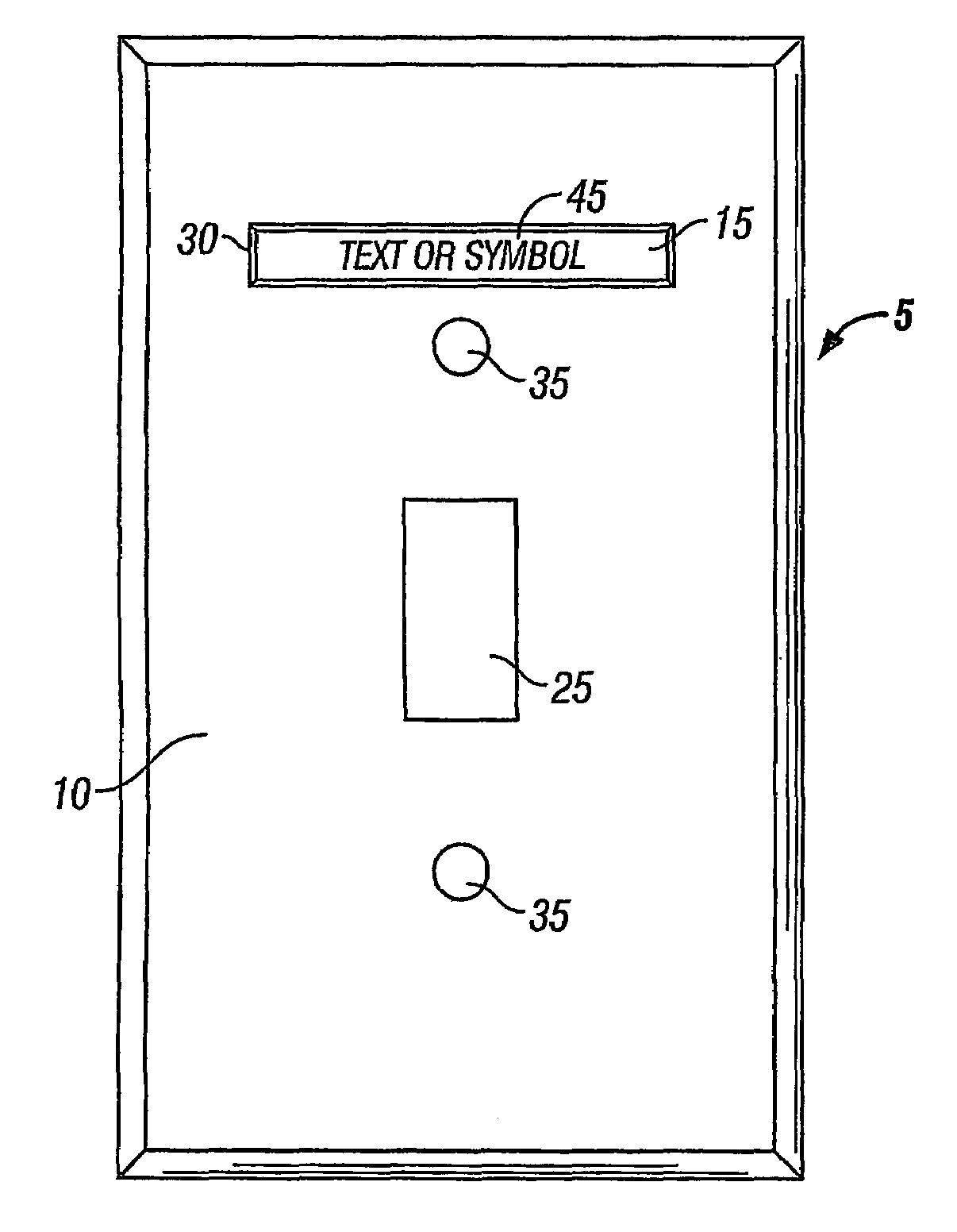
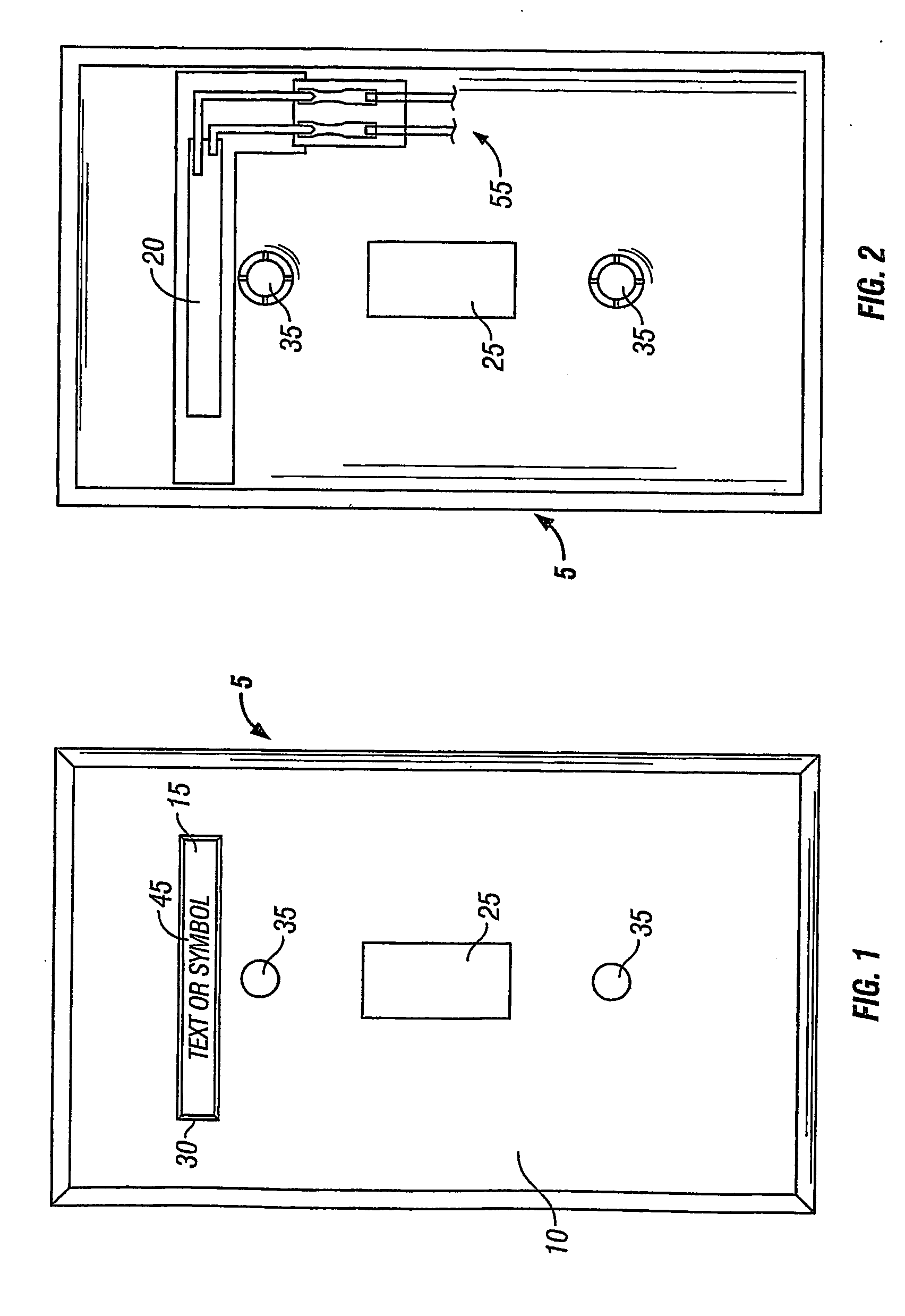
[0012]An embodiment of the invention is described with respect to FIG. 1, in which a backlit cover plate 5 comprises a plate 10, a window cover 15, which cover engages the edges of the window 30 thereby permitting the electroluminescent (EL) backlighting 20, more clearly shown in FIG. 2, to emit light through the window 30. Label 45, which displays either text or symbols, is positioned between the EL backlighting 20 and window cover 15 is thereby contrasted and highlighted. Plate 10 has a switch opening 25, a window 30, and at least one plate-securing opening 35. As shown, screws, nails or any other suitable fasteners may be used to secure the plate 10 to a surface through plate-securing openings 35. As previously noted, window 30 is an opening in plate 10, but may also be formed with transparent material (not shown) in lieu of window cover 15. The contrasting text or symbols on label 45 would then be attached to the top of the backlit window 30 without departing from the spirit or ...


PUM


Abstract

A cover plate (5) for use with an electrical supply. In one embodiment, the backlit cover plate comprises a plate (5), the plate (5) including a window (15) therein; and backlighting, the backlighting powered by the electrical supply (55), the backlighting (20) disposed to be mounted on the plate (5) so as to shine through the window (15). Optional labels (45) may be provided through which the backlighting may shine, thereby illuminating data on the labels (45) from behind. In a disclosed embodiment, the backlighting (20) comprises electroluminescent lighting.

Description

RELATED APPLICATIONS[0001]Applicant claims priority to Provisional Application No. 60 / 355,443, filed Feb. 7, 2002 in the United States Patent and Trademark Office.FIELD OF THE INVENTION[0002]This application relates generally to the field of electrical fixtures, and more specifically to backlighting for electrical cover plates and embodiments of same using techniques such as electroluminescence.BACKGROUND OF THE INVENTION[0003]In both homes and commercial establishments, cover plates are conventionally attached to the walls or other surfaces to cover the electrical connections of switches and power outlets. Securing of the cover plate is well known in the art. Typically, the cover plate is secured to the receiving surface by two screws. In an example of a light switch, as is well known, a light is typically turned on and off by flipping the light switch in the appropriate on or off position. It is common for several switches to be located in one general region, such as a door. In or...

Claims


Application Information

Patent Timeline
Patent Type & Authority Patents(United States)
IPC IPC(8): F21V33/00G09F13/20H01H9/02H01H9/18G09F13/04G09F13/22H01H9/16
CPCG09F13/04G09F13/22H01H9/161H01H9/182H01H2009/186H01H2219/006H01H2219/008H01H2219/018
Inventor JASPER, MICHAEL
Owner HEATHER LEIGH BRANTLEY TRUSTEE FOR THE BRANTLEY CHILDREN TRUST A TEXAS TRUST
Why Eureka
Try Eureka