Multi-leaf collimators

a collimator and multi-leaf technology, applied in the field of multi-leaf collimators, can solve the problems of high frictional load of the leadscrew, short oscillation of the long free end of the leadscrew, so as to reduce production costs and assembly times, drive a greater amount of leaves, and reduce the effect of production cost and assembly tim

Inactive Publication Date: 2009-10-22
ELEKTA AB
View PDF3 Cites 24 Cited by
  • Summary
  • Abstract
  • Description
  • Claims
  • Application Information

AI Technical Summary

Benefits of technology

[0018]The present invention therefore seeks to provide a compact MLC actuator, that addresses many of the problems associated with a conventional leadscrew system, with the potential to drive a greater amount of leaves without relying on a complex drive design and a high parts count (relative to the number of leaves). This has the benefit of reducing production costs and assembly times. The drive mechanism should ideally not reduce the shielding effect of the tungsten leaves or interfere with the radiation beam. A modular design would also improve servicing issues by allowing the complete removal of the drive system from the leafbank.
[0022]Mounting the drive motors in this way allows them to be distributed more space-efficiently, and allows the drive system to be modular, without requiring rack and pinion gears.
[0024]Still greater space efficiency can be achieved by including a lower subframe, mounted at a location spaced from the leaf array in an opposite direction to that of the upper array and on which the remainder of the motors are mounted. This can be designed in a generally similar manner to that of the (upper) subframe, except as regards the leaf pitch which will need to be adjusted as a result of the varying inclination of the leaves. We prefer that half of the leaves are driven from the subframe and half are driven from the lower subframe. Adjacent leaves in the array can be driven alternately from the subframe and from the lower subframe.
[0027]The drive means can further include a threaded member on the leadscrew. This can urge a laterally extending lug, thereby to drive the leaf. The lug can engage with a recess on the leaf edge. It can be held in machined slot in the subframe; that slot can be machined with non-parallel sides to assist in guiding the lug in the light of the offset nature of the load that it needs to carry.

Problems solved by technology

This is directed towards a cancerous region of the patient, and adversely affects the tumour cells causing an alleviation of the patient's symptoms.
Due to the small engagement area of the thread, the leadscrew therefore experiences high frictional loads and requires regular lubrication to maintain an acceptable service life.
The performance of the leadscrew is also adversely affected by a whipping motion that can arise when the leaf nut is close to the motor, in which the long free end of the leadscrew can oscillate as it rotates.
In addition, the leadscrew experiences a buckling load when the leaf is pushed to far end of the leadscrew.
There is also a certain degree of noise due to this motion of the leadscrew.
A lead screw system as used on the MLC would not be a viable solution as it would require a 1.5 mm diameter leadscrew; as the leaf travel is longer, the leadscrew would suffer increased whipping and buckling.
Leadscrews with a high aspect ratio are also extremely difficult and costly to manufacture and are likely to fracture if they are not adequately supported.
In addition, the quantity of motors required (40 per side) could not be fitted in behind the leaves due to their size.
Removal of the leaf bank is a lengthy process, and problems can occur with radiation performance if the leaf bank is not replaced in the same position.
This has the undesired effect of reducing the shielding effect of the leaf, as some 8 mm is lost off the top / bottom of the leaf for the rack and bearing surface.
This clearance can vary leaf to leaf, depending on manufacturing tolerances, and can lead to unwanted backlash once the pinion and motor gearbox begin to wear.
Such backlash will affect the positional accuracy of the leaves.
However, as it incorporates a rack and pinion system it will suffer from backlash in the same way.
The MLC Rack and Pinion System was originally designed around a 160 leaf MLC, but limitations in available space in the Treatment Head above and below the leafbank as well as restrictions on the overall head diameter create problems for fitting this type of Actuator.
The gear racks in the actuator are positioned to match the leaf pitch; during operation the racks extend into the radiation beam, which may have effects on beam performance—particularly if there is an error in the pitching.
The Actuator module also contains a high parts count, including many precision cut gears and racks making this expensive to produce.
Thus, the leaf thickness / pitch and motor size affects the method in which the actuation is carried to the leaf, and once a suitable method is derived (of the 2 practical drive solutions, leadscrew and rack and pinion) the design can have inherent problems with wear, noise, production and assembly costs, backlash and servicing issues.

Method used


Image

  • Multi-leaf collimators
  • Multi-leaf collimators
  • Multi-leaf collimators

Examples


Embodiment Construction

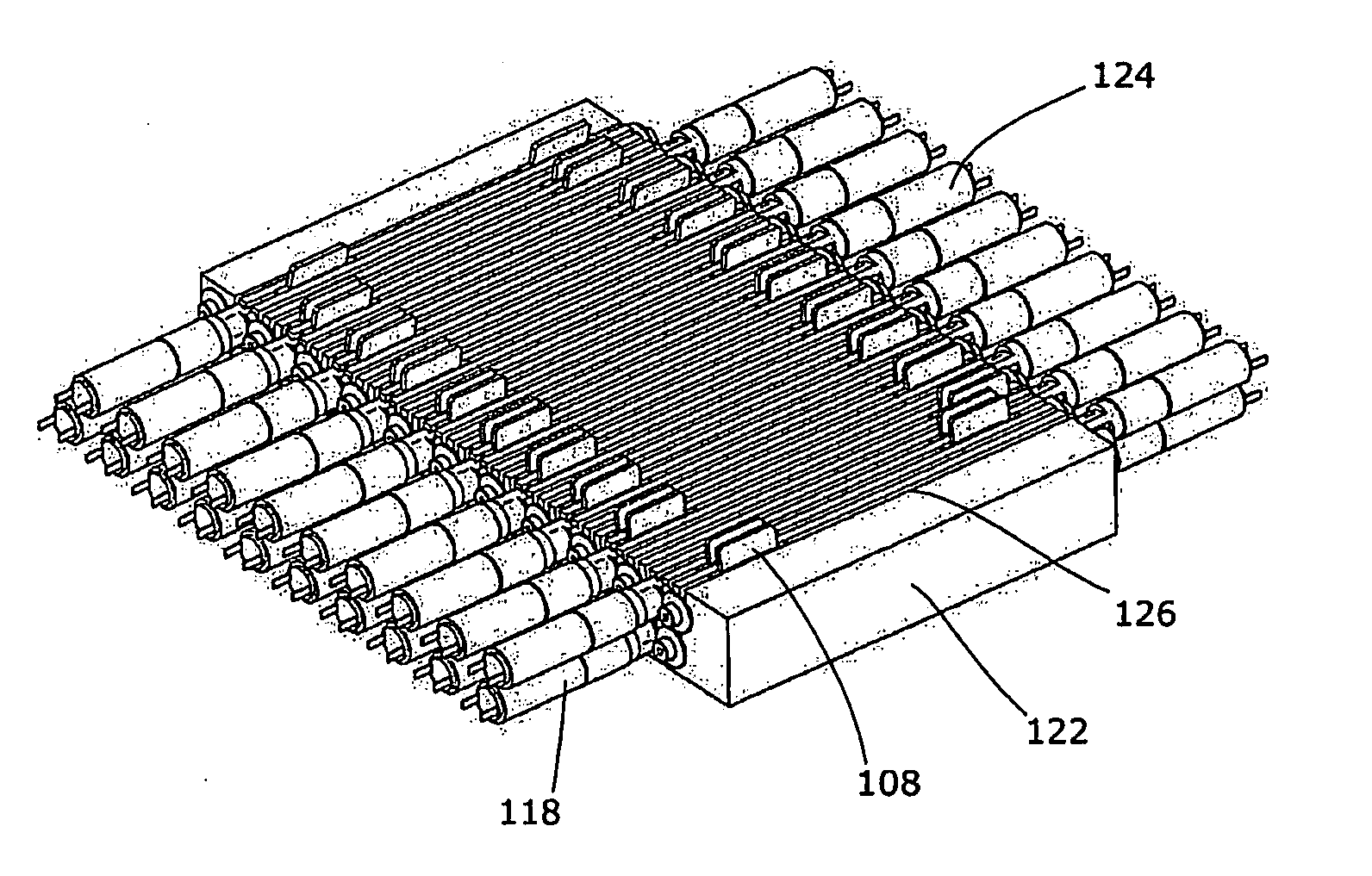
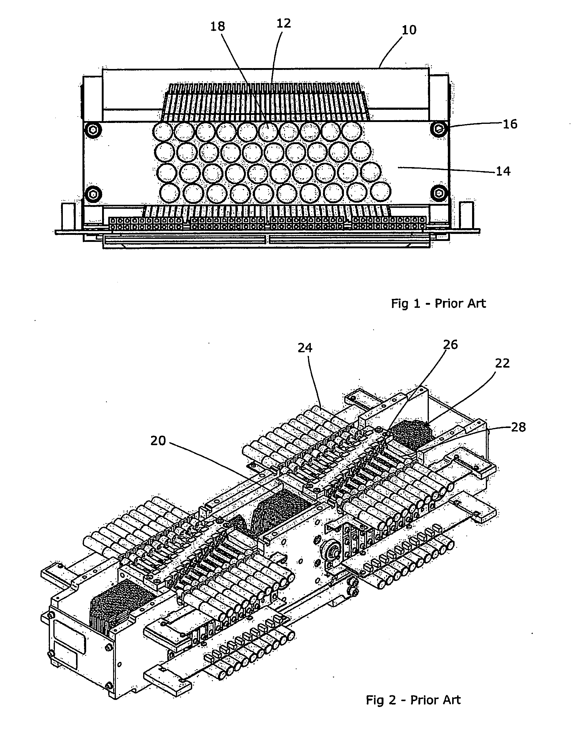
[0037]The inherent limitation on the minimum length of the rack and pinion-type system is the quantity of the motors mounted on the side of the module. For example, assuming that each module is designed to drive 40 leaves, that each motor is 10 mm in diameter and (therefore) spaced 14 mm apart in a double row, then the length of the module will have to be 14×(40 / 2), i.e. 280 mm, plus the distance over which the leaves are expected to travel. If we take a rough figure of 70 mm for this distance, this makes an overall length for the system of 350 mm. The minimum overall height will be the motor diameter plus the height of the rack, i.e. about 32 mm. A rack and pinion module when mounted on the leafbank will therefore increase the treatment head diameter significantly.

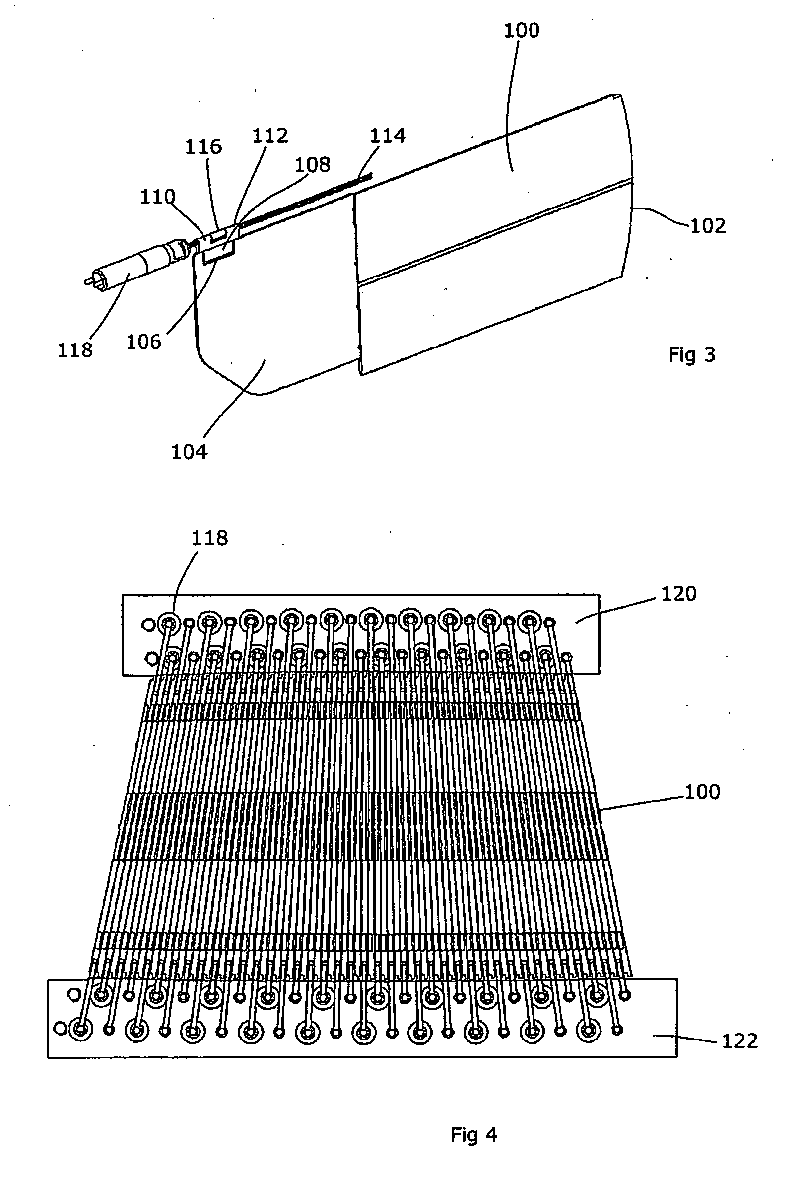
[0038]The MLC actuator described herein features a lead screw that runs parallel to the leaf, which means that the length of the drive modules are shorter overall, as the leadscrew only needs to be a slightly longer than ...


PUM


Abstract

A multi-leaf collimator for a radiotherapy apparatus comprises at least one array of laterally-spaced elongate leaves, each leaf being driven by an associated motor connected to the leaf via a drive means so as to extend or retract the leaf in its longitudinal direction, the drive means comprising a sub-frame on which at least a subset of the motors are mounted, the sub-frame being mounted at a location spaced from the leaf array in a direction transverse to the lateral and longitudinal directions, and including a plurality of leadscrews disposed longitudinally, each being driven by a motor and being operatively connected to a leaf thereby to drive that leaf.

Description

CROSS-REFERENCE TO RELATED APPLICATION[0001]The present application is a CIP of and claims priority of International Application No. PCT / EP2008 / 003183, filed Apr. 21, 2008, and published in English the content of which is hereby incorporated by reference in its entirety.FIELD OF THE INVENTION[0002]The present invention relates to multi-leaf collimators.BACKGROUND ART[0003]Radiotherapeutic apparatus involves the production of a beam of ionising radiation, usually x-rays or a beam of electrons or other sub-atomic particles. This is directed towards a cancerous region of the patient, and adversely affects the tumour cells causing an alleviation of the patient's symptoms. Generally, it is preferred to delimit the radiation beam so that the dose is maximised in the tumour cells and minimised in healthy cells of the patient, as this improves the efficiency of treatment and reduces the side effects suffered by a patient. A variety of methods of doing so have evolved.[0004]One principal com...

Claims


Application Information

Patent Timeline
Patent Type & Authority Applications(United States)
IPC IPC(8): G21K1/04
CPCA61N5/1042G21K1/046G21K1/04
Inventor BROAD, MARTINFURTH, MARK ALEXANDER
Owner ELEKTA AB
Why Eureka
Try Eureka