Method for the production of a brake disk and brake disk

a technology of brake disks and cylinders, which is applied in the direction of brake discs, brake types, mechanical devices, etc., can solve the problems of complicated procedure, excessive wear, and limited radial expansion by rigid retaining bolts

Inactive Publication Date: 2008-12-23
DAIMLER AG
View PDF12 Cites 16 Cited by
  • Summary
  • Abstract
  • Description
  • Claims
  • Application Information

AI Technical Summary

Benefits of technology

[0015]The bodies inserted into one another preferably have a round, particularly preferably circular, cross section. Accordingly their geometric shape is cylindrical, an outer body being designed as a hollow cylinder (bushing) and an inner body also as a hollow cylinder or as a solid cylinder (bolt). Such an arrangement is advantageous for unimpeded mobility of the bodies with respect to one another.

Problems solved by technology

Brake noise and excessive wear in disk brake systems are often attributable to the phenomenon of shielding.
Although in this brake disk there is a separation between hub and friction ring, the radial expansion is limited by the rigid retaining bolts.
The disadvantage here is the complicated procedure, and a tight axial fit is difficult to ensure.

Method used


Image

  • Method for the production of a brake disk and brake disk
  • Method for the production of a brake disk and brake disk
  • Method for the production of a brake disk and brake disk

Examples


Embodiment Construction

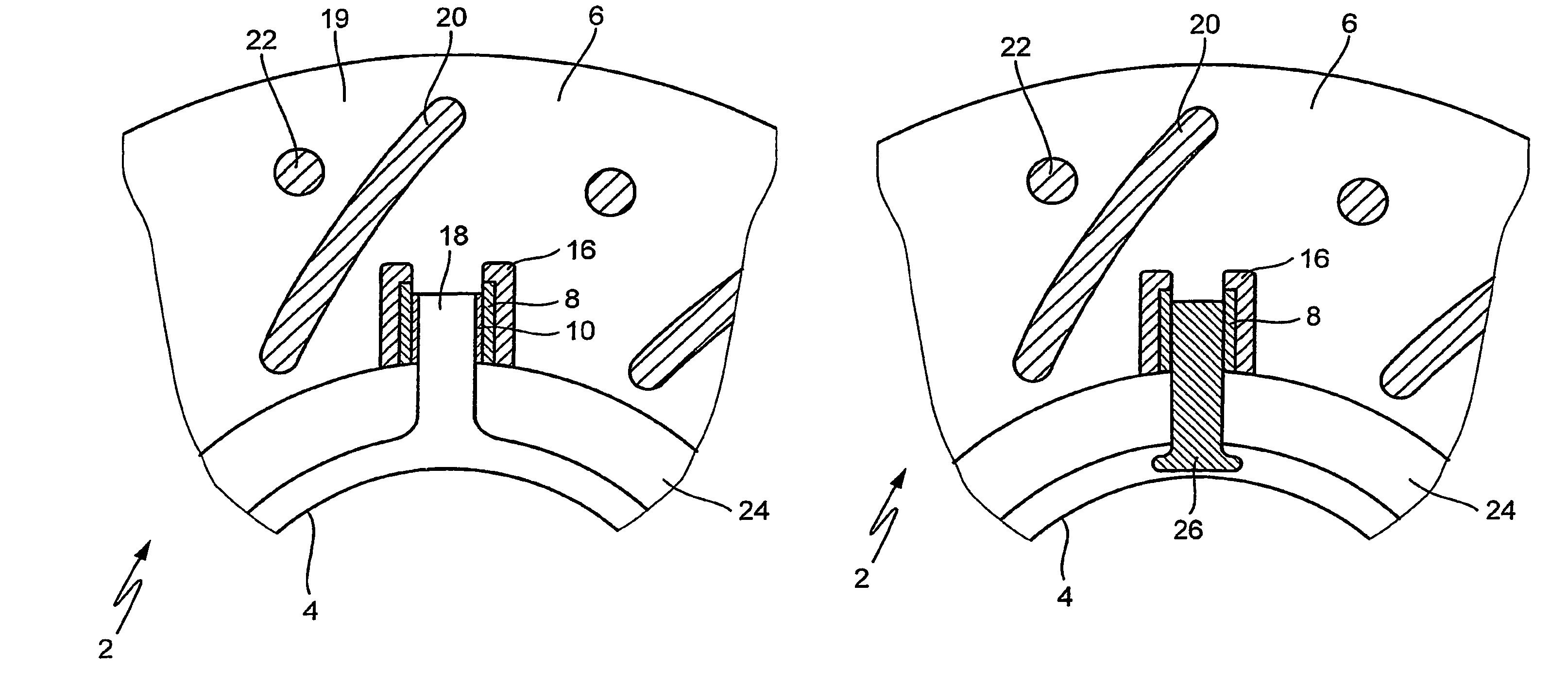
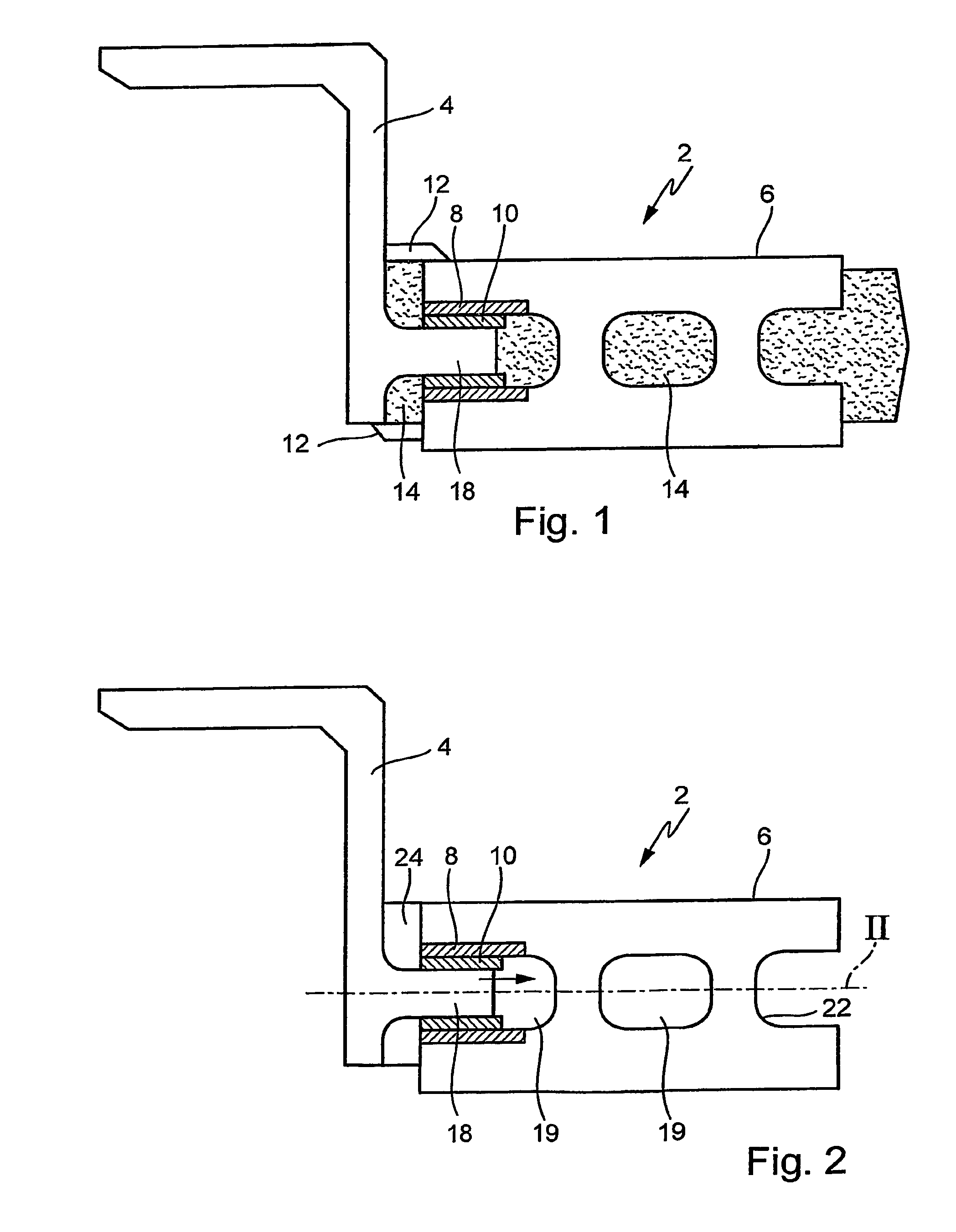
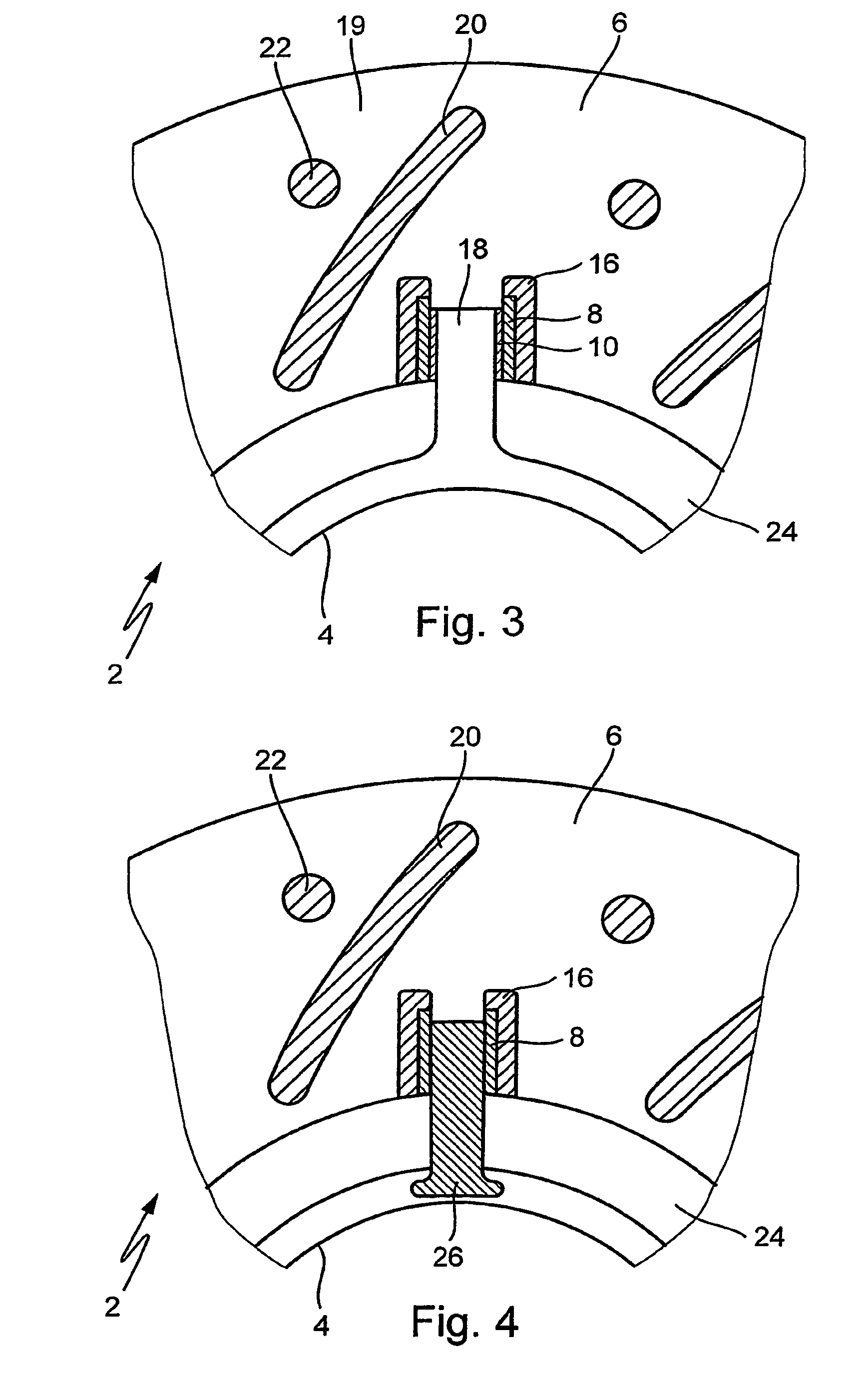
[0021]Ten pairs of two bodies each inserted into one another in the shape of cylindrical bushing pairs are placed in a core box in an annular shape (8, 10 in FIG. 1). Core sand is shot into the core box and solidified. A solidified casting core (core) encloses bushing pairs 8, 10 in some areas, whereby bushing pairs 8, 10 are fixed in the core and become an integral part thereof.

[0022]The core is placed in a casting mold; the brake disk is cast using a method known per se. The metal is cast from a bottom of a friction ring area; the melt flows upward via bridge channels, which form bridges 12 in the cast brake disk, to a hub area. The cast brake disk is then cooled down in a controlled manner.

[0023]FIG. 1 shows a cross section of an unfinished brake disk 2 after casting, core 14 being still enclosed by brake disk 2. Brake disk 2 has a brake disk hub (hub) 4 and a friction ring 6. Hub 4 and friction ring 6 are joined via bridges 12 in this state.

[0024]Core 14 is molded in such a way ...


PUM

PropertyMeasurementUnit
radial thermal expansionaaaaaaaaaa
axis of movementaaaaaaaaaa
shrinkageaaaaaaaaaa

Abstract

A method for the production of a brake disk and a brake disk which are characterized by the following features: several pairs of bushings inserted into each other are placed into a core box. The core is closed about the bushings in such a way that they form an integral component of the core. The core is inserted into a casting tool and the brake disk is cast. After the core is removed, the brake disk hub and the friction ring are decoupled from each other and can expand in relation to each other without shielding the brake disk.

Description

[0001]The present invention relates to a method for manufacturing a cast brake disk and to a brake disk made of a cast material.BACKGROUND[0002]Brake noise and excessive wear in disk brake systems are often attributable to the phenomenon of shielding. Shielding is understood as an axial distortion of the brake disk caused by radial thermal expansion.[0003]Shielding may be reduced considerably by decoupling the friction ring from the brake disk hub. DE 199 31 140 A1, for example, describes the manufacture of a composite cast brake disk made of a hub and a friction ring. A hub is provided in this case with radial retaining bolts and is placed into a casting mold. A casting is then made around the hub in the region of the retaining bolts, and the friction ring is formed. Although in this brake disk there is a separation between hub and friction ring, the radial expansion is limited by the rigid retaining bolts.[0004]DE 195 05 112 A1 describes a method for composite casting for a brake ...

Claims


Application Information

Patent Timeline
Patent Type & Authority Patents(United States)
IPC IPC(8): F16D65/12B22D19/12
CPCB22D19/12F16D65/12F16D2065/1328F16D2250/0007
Inventor BOTSCH, SIEGFRIED
Owner DAIMLER AG
Why Eureka
Try Eureka