Methods and apparatus for conducting electrical current

a technology of electrical current and conductor, applied in the field of biomedical analysis, can solve the problems of mismanagement of living subjects, and reducing the accuracy of the determined cardiac output, so as to facilitate the electrical coupling of the terminal and facilitate the retention of the terminal

Active Publication Date: 2007-09-18
FUJIFILM SONOSITE
View PDF14 Cites 51 Cited by
  • Summary
  • Abstract
  • Description
  • Claims
  • Application Information

AI Technical Summary

Problems solved by technology

However, because the electrode terminals are the same size, connectors may be inadvertently coupled to the wrong electrode terminal, such that the circuit is reversed.
More specifically, the electrical connector coupled to the current source may be inadvertently coupled to the measurement terminal and the electrical connector coupled to the measurement device may be inadvertently coupled to the stimulation terminal.
Coupling the electrical connectors to the wrong terminal may decrease an accuracy of the impedance measurement, which may decrease an accuracy of the determined cardiac output and / or may cause mismanagement of the living subject.

Method used


Image

  • Methods and apparatus for conducting electrical current
  • Methods and apparatus for conducting electrical current
  • Methods and apparatus for conducting electrical current

Examples


Embodiment Construction

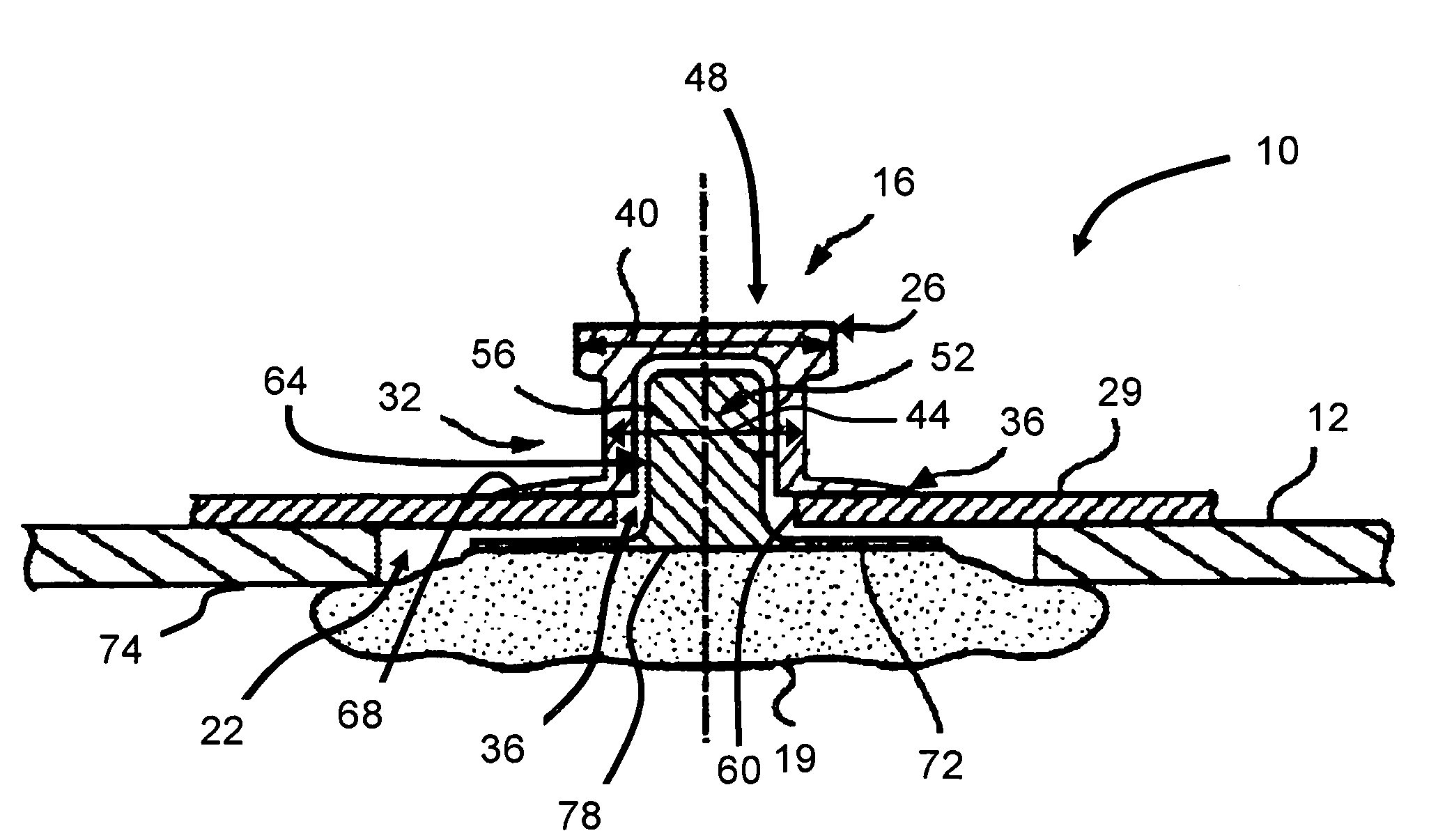
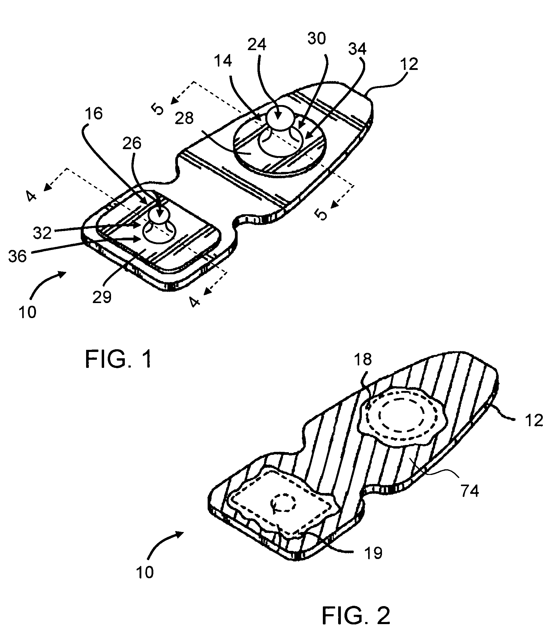
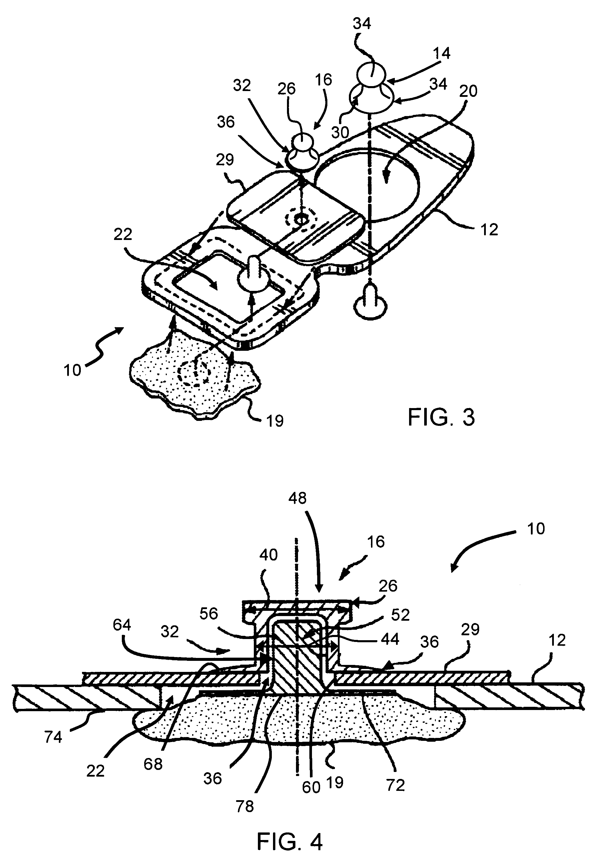
[0023]FIG. 1 is a top perspective view of an exemplary embodiment of an electrode assembly 10 for use with a living subject (not shown in FIG. 1). FIG. 2 is a bottom perspective view of electrode assembly 10. FIG. 3 is a partial exploded perspective view of electrode assembly 10. FIG. 4 is a cross-sectional view of a portion of electrode assembly 10 taken along line 4-4 (shown in FIG. 1). FIG. 5 is a cross-sectional view of a portion of electrode assembly 10 taken along line 5-5 (shown in FIG. 1). Electrode assembly 10 generally includes a substrate 12, a plurality of terminals 14 and 16 for conducting electrical current, and a plurality of electrolytic elements 18 and 19. Although only two terminals 14 and 16 are illustrated, electrode assembly 10 may include any number of terminals. As will be describe in more detail below, terminals 14 and 16 are sized differently to facilitate coupling of components to terminals 14 and / or 16 in the correct orientation. More specifically, because...


PUM


Abstract

An electrode assembly for use with a living subject includes a substrate having first and second openings extending therethrough, and a first terminal at least partially received within the first opening. The first terminal includes an end portion having a first size. At least a portion of the first terminal configured to conduct electrical current. A second terminal is at least partially received within the second opening. The second terminal includes an end portion having a second size that is different than the first size of the first terminal end portion. At least a portion of the second terminal is configured to conduct electrical current. The assembly also includes a first electrolytic element configured to transfer electrical current between the skin of a living subject and the first terminal, and a second electrolytic element configured to transfer electrical current between the skin of a living subject and the second terminal.

Description

BACKGROUND OF THE INVENTION[0001]This invention relates generally to biomedical analysis, and more specifically to methods and apparatus for conducting electrical current through a living subject to determine a property of the living subject.[0002]At least some known methods use impedance cardiography to non-invasively determine cardiac output estimates. For example, impedance cardiography, sometimes referred to as thoracic bioimpedance or impedance plethysmography, may be used to measure the stroke volume of a heart. The stroke volume can then be multiplied by heart rate, for example obtained using an electrocardiogram (ECG), to obtain cardiac output. At least some known methods of measuring the stroke volume include modeling thoracic, or chest cavity, impedance ZT(t) as a constant impedance, Z0, and as a time-varying impedance, ΔZ(t). Changes in the impedance over time can be related to a change in fluidic volume, and ultimately stoke volume and cardiac output.[0003]In at least so...

Claims


Application Information

Patent Timeline
Patent Type & Authority Patents(United States)
IPC IPC(8): H01R4/48
CPCA61B5/04087A61B5/0416H01R4/4854H01R4/5066H01R11/22H01R13/506H01R13/6275H01R2201/12H01R2201/20Y10S439/909A61B5/259A61B5/274
Inventor BRADLEY, PATRICK WALTONBAURA, GAIL DAWN
Owner FUJIFILM SONOSITE
Why Eureka
Try Eureka