Adjustable mounting bracket assembly for mounting an electrical box

a technology for mounting brackets and electrical boxes, which is applied in the direction of machine supports, electrical apparatus casings/cabinets/drawers, coupling device connections, etc. it can solve the problems of inability to employ direct stud mounting methods, inability to guarantee the height of all the boxes installed in this fashion, and inability to ensure the height of all the boxes. the effect of structural strength

Active Publication Date: 2007-09-18
THOMAS & BETTS INT INC
View PDF44 Cites 56 Cited by
  • Summary
  • Abstract
  • Description
  • Claims
  • Application Information

AI Technical Summary

Benefits of technology

[0010]The mounting plate can include an opening for a second electrical box and a plurality of mounting hole apertures for securing the electrical box to the mounting plate. Typically, the openings for the electrical boxes are located in the central portions of the mounting plate and are spaced a sufficient distance apart so that the structural strength of the mounting plate is maintained. The structural strength of the mounting plate is augmented by the side walls which stiffen the mounting plate and resist twisting under the weight of the electrical boxes.

Problems solved by technology

However, there is no guarantee that all the boxes installed in this fashion will be the same height off the floor.
Also, there is no guarantee that all the boxes will be positioned at the same depth within the wall cavity.
However, if the architectural plans call for the box or boxes to be mounted some distance from a stud, then methods requiring direct stud-mounting cannot be employed.
In either case, once a particular electrical box size is selected and secured to the bracket, the installer is limited to using only a correspondingly sized dry-wall ring or other cover attachment.
This is an added expense for the user.
Moreover, when a bracket is mounted between studs having non-standard center-to-center dimensions, the user may have to add additional framing before he can install the bracket.
Adjustable brackets that have been used in the past do not have the strength and rigidity of non-adjustable brackets and, therefore, have not been widely used.

Method used


Image

  • Adjustable mounting bracket assembly for mounting an electrical box
  • Adjustable mounting bracket assembly for mounting an electrical box
  • Adjustable mounting bracket assembly for mounting an electrical box

Examples


Embodiment Construction

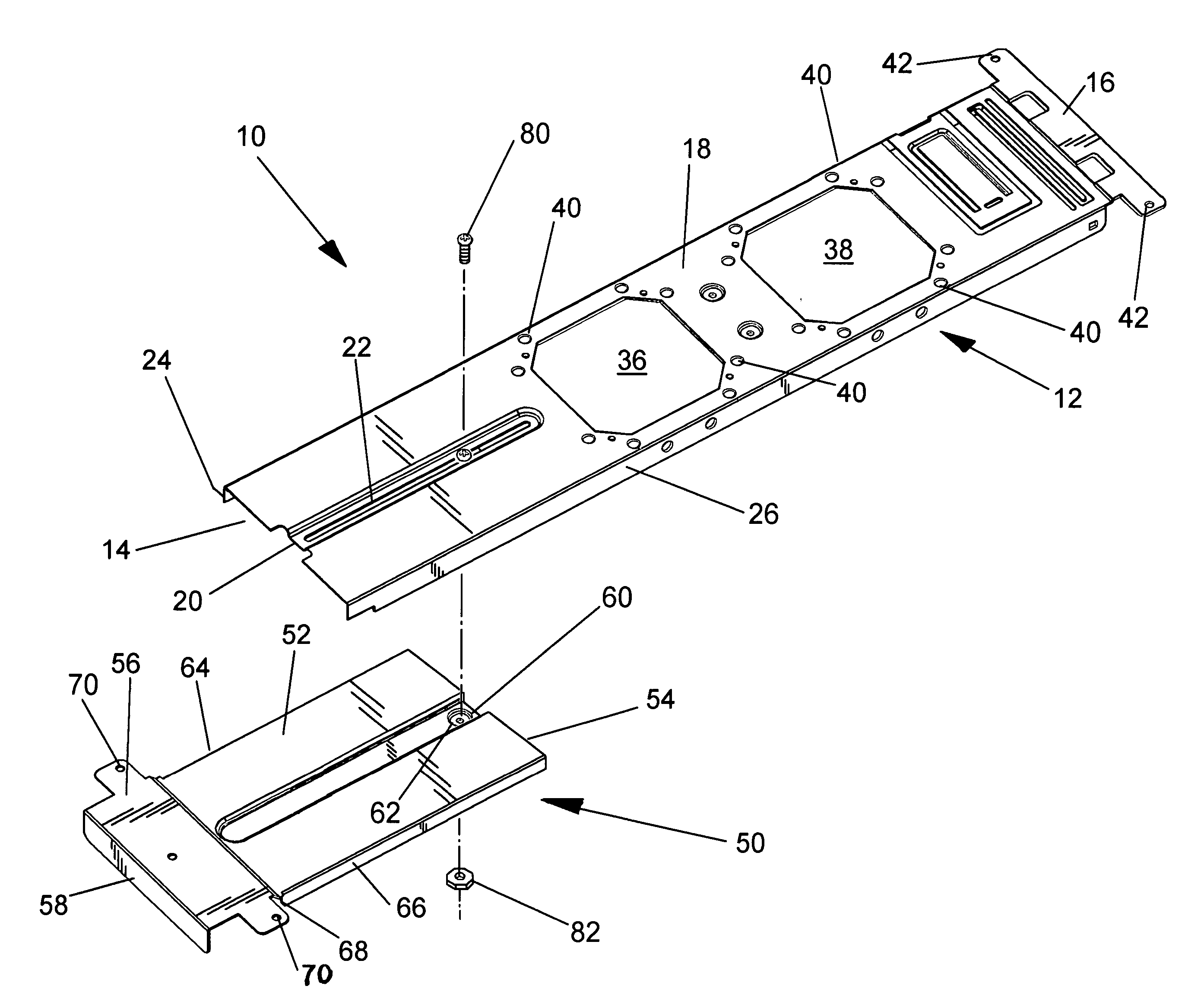
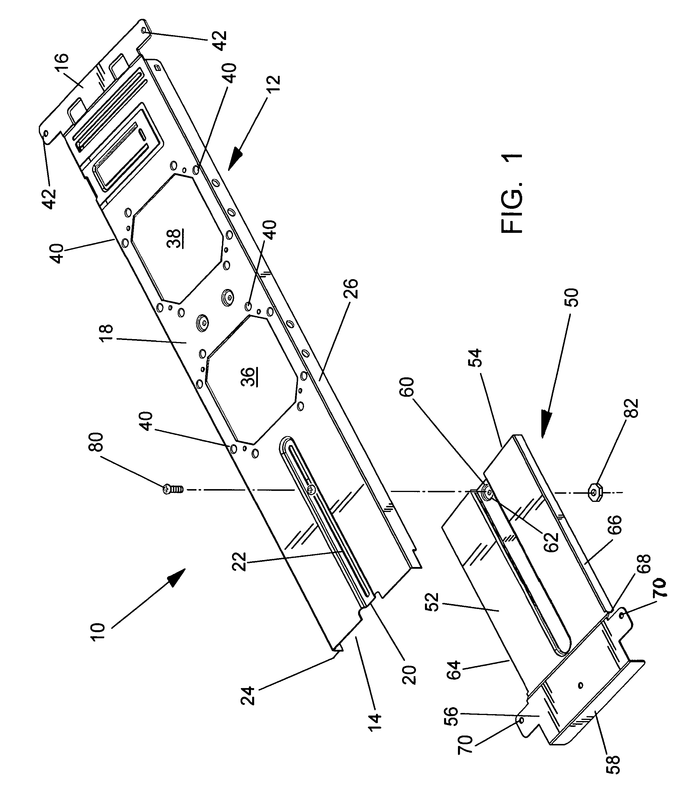
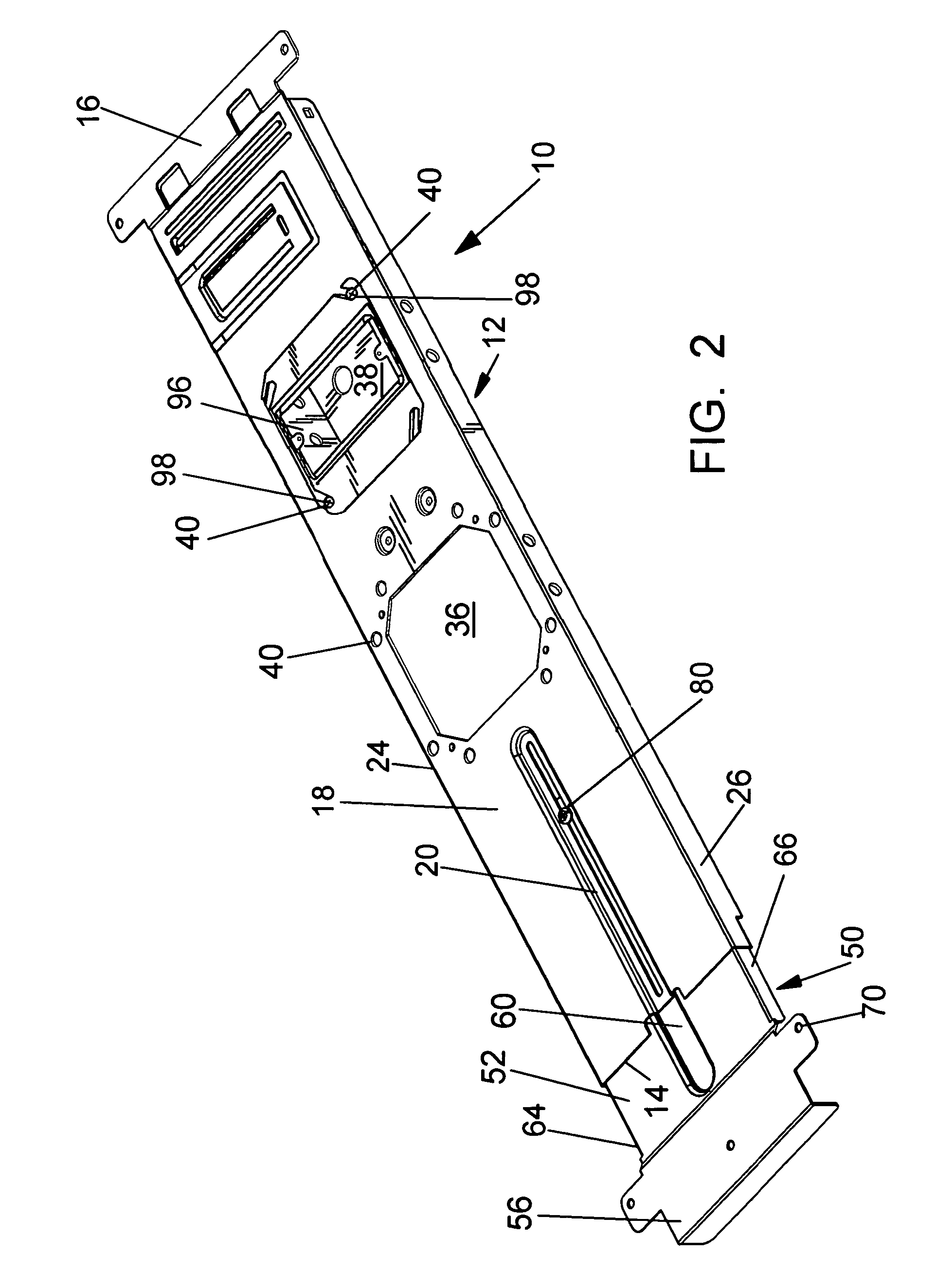
[0023]The present invention is directed to an adjustable mounting bracket assembly for mounting electrical boxes to a structure. In many cases when an electrical box is mounted in a wall, floor or ceiling, the location selected for the electrical box is not adjacent to a structure that can support the electrical boxes. In these cases, the electrical box is installed in a mounting bracket which is then attached to one or more structural supports. The adjustable bracket assembly of the present invention can be adjusted to vary the distance between the opposing ends so that a single bracket assembly can be used for multiple applications. The adjustable bracket assembly includes a mounting bracket and an adapter plate that are slidably joined to allow the distance between the opposing ends to be adjusted to correspond to different structures.

[0024]The adjustable bracket assembly is intended to be attached to wood or metal wall studs in either a horizontal or vertical configuration. When...


PUM


Abstract

An adjustable mounting bracket assembly for mounting an electrical box that includes: (a) a mounting bracket that includes a mounting plate having a first opening for receiving an electrical box and a rail having a first aperture; a mounting bracket attaching end; a mounting bracket mating end; a first pair of side walls and a pair of tabs; (b) an adapter plate that includes: a base plate having a track with a second aperture; an adapter plate attaching end; an adapter plate mating end; and a second pair of side walls; and (c) a fastener. The mounting bracket mating end slidably receives the adapter plate mating end and the first aperture in the rail aligns with the second aperture in the track. The fastener is inserted in the first and second apertures and tightened to secure the mounting bracket to the adapter plate.

Description

[0001]This application is a continuation-in-part application of application Ser. No. 10 / 944,529, filed on Sep. 17, 2004, which claims priority from U.S. Provisional Application No. 60 / 507,024, filed on Sep. 29, 2003, and U.S. Provisional Application No. 60 / 561 / 641, filed on Apr. 13, 2004, all of which are incorporated herein in their entirety.FIELD OF THE INVENTION[0002]This invention pertains to an adjustable mounting bracket assembly for mounting electrical boxes within walls, floors or ceilings and, more particularly, to an adjustable mounting bracket assembly employing a mounting bracket to which one or more electrical boxes are secured and an adapter plate which adjustably receives the mounting bracket.BACKGROUND OF INVENTION[0003]There are many different methods used to secure electrical boxes to the walls, floor or ceilings of a structure, such as a building. When studs are used to frame the structure, the most common method used is to secure the box directly to the stud. The...

Claims


Application Information

Patent Timeline
Patent Type & Authority Patents(United States)
IPC IPC(8): H01H9/02H02G3/12
CPCH02G3/125Y10S248/906
Inventor DINH, CONG
Owner THOMAS & BETTS INT INC
Why Eureka
Try Eureka