Objective lens driving apparatus used with an optical pickup

a driving apparatus and optical pickup technology, applied in the direction of instruments, data recording, disposition/mounting of heads, etc., can solve the problems of not directly controlling unable to accurately capture the light spot, and unable to directly control the incident angle of light with respect to the recording surface of the disk. achieve the effect of smooth control of the driving of an objective lens without increasing the size of the apparatus or the weight of the driving portion

Inactive Publication Date: 2007-09-18
SAMSUNG ELECTRONICS CO LTD
View PDF34 Cites 8 Cited by
  • Summary
  • Abstract
  • Description
  • Claims
  • Application Information

AI Technical Summary

Benefits of technology

[0011]In order to solve the above and / or other problems, it is an aspect of the present invention to provide an objective lens driving apparatus of an optical pickup which can smoothly control driving of an objective lens without increasing the size of the apparatus or the weight of a driving portion.

Problems solved by technology

If the incident direction of light is inclined, an accurate light spot cannot be formed on the disk and, an error is generated in recording and reproduction of data.
However, the objective lens driving apparatus maintains the focus of a light spot by maintaining a constant distance between the objective lens and the recording surface of the disk and controls the light spot to follow a desired track, but it does not directly control an incident angle of the light with respect to the recording surface of the disk.
In the above structure, since constituent elements of the tilt adjustment mechanism, such as the tilt coils 15a and 15b, are installed in an additional space on the base 10 separated from the space for the focus and tracking adjustment mechanism, it is difficult to make a compact objective lens driving apparatus.

Method used


Image

  • Objective lens driving apparatus used with an optical pickup
  • Objective lens driving apparatus used with an optical pickup
  • Objective lens driving apparatus used with an optical pickup

Examples


Embodiment Construction

[0026]Reference will now made in detail to the present preferred embodiments of the present invention, examples of which are illustrated in the accompanying drawings, wherein like reference numerals refer to the like elements throughout. The embodiments are described below in order to explain the present invention by referring to the figures.

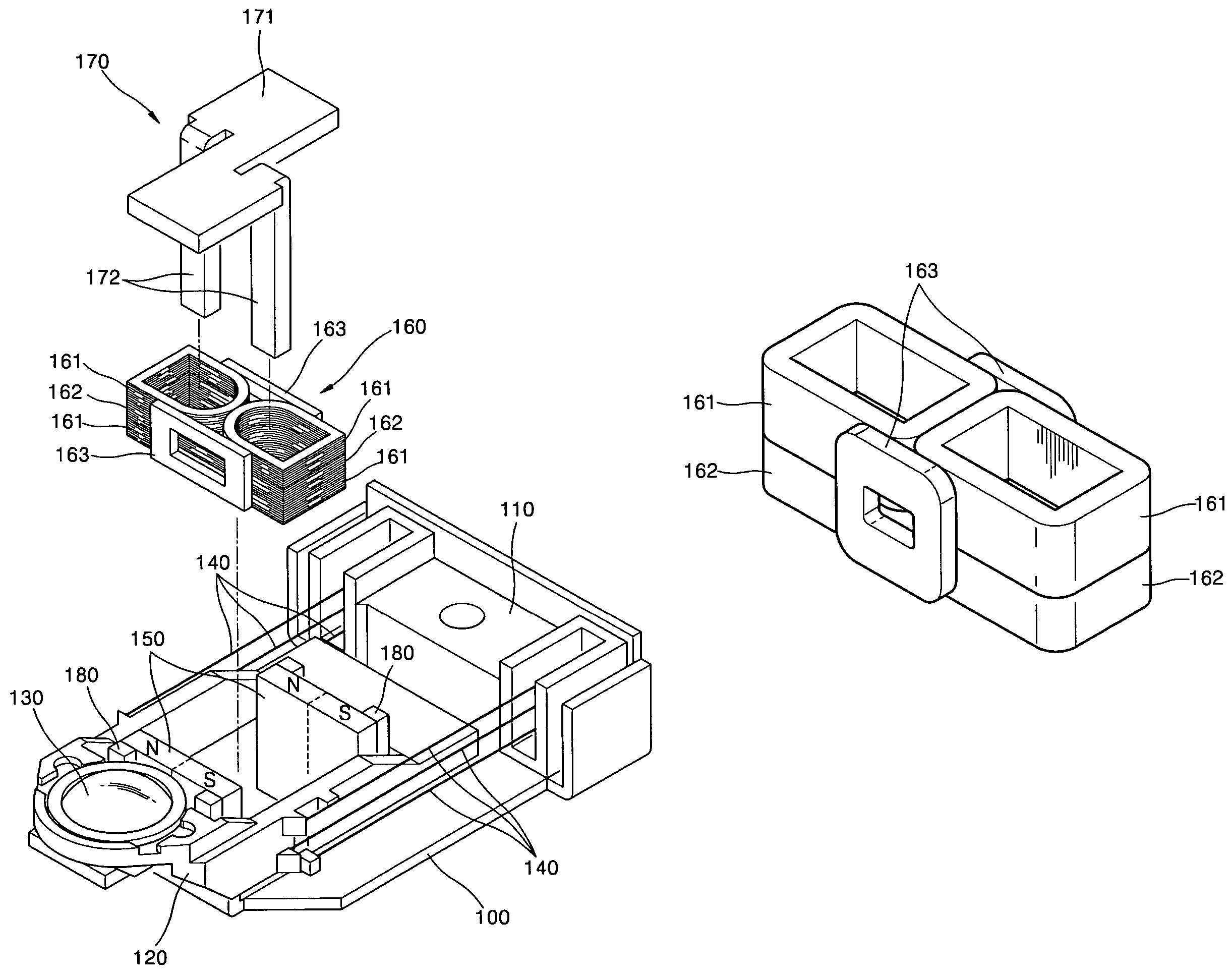
[0027]Referring to FIGS. 3 and 4, a holder 110 is provided on a base 100. A blade 120 on which an objective lens 130 is mounted is supported by a plurality of wires 140 capable of elastically moving with respect to the holder 110. A pair of outer yokes 180 are installed on the base 100 and a pair of magnets 150 are installed at the outer yokes 180 to face each other. A coil assembly 160 is installed at the center portion of weight of the blade 120 and is arranged between the magnets 150.

[0028]Each of the magnets 150 is polarized into two poles. The magnets 150 are installed such that the same poles of the magnets 150 face each other. The coil as...


PUM

PropertyMeasurementUnit
gravityaaaaaaaaaa
incident angleaaaaaaaaaa
electromagnetic forceaaaaaaaaaa

Abstract

An objective lens driving apparatus used with an optical pickup includes a base, a holder provided on the base, a blade on which an objective lens is mounted, an elastic support body elastically supporting the blade and which is capable of moving with respect to the holder, a pair of magnetic members installed on the base to face each other, and a coil assembly including a focus coil, a tracking coil, and a tilt coil, the coil assembly being installed at the blade so as to be disposed between the magnetic members. Thus, coils needed to change the position of an objective lens are incorporated into a single coil assembly and are arranged between a pair of magnets, and an installation space is small so that the apparatus can be made compact.

Description

CROSS-REFERENCE TO RELATED APPLICATIONS[0001]This application is a continuation in part of U.S. patent application Ser. No. 10 / 622,785, filed Jul. 21, 2003, now abandoned, which claims the benefit of Korean Patent Application No. 2002-50305, filed Aug. 24, 2002 in the Korean Intellectual Property Office, the disclosures of which are incorporated herein by reference. This application further claims the benefit of Korean Patent Application No. 2002-50305, filed Aug. 24, 2002 in the Korean Intellectual Property Office, and Korean Patent Application No. 2003-55873, filed Aug. 12, 2003 in the Korean Intellectual Property Office, the disclosures of which are incorporated herein by reference.BACKGROUND OF THE INVENTION[0002]1. Field of the Invention[0003]The present invention relates to an objective lens driving apparatus used with an optical pickup.[0004]2. Description of the Related Art[0005]In general, disk drives record and / or reproduce information to and / or from a disk or a recording ...

Claims


Application Information

Patent Timeline
Patent Type & Authority Patents(United States)
IPC IPC(8): G11B7/08G11B7/085G11B7/09G11B7/00
CPCG11B7/0933G11B7/0935G11B7/0956
Inventor CHEONG, YOUNG-MINKIM, KWANGKIM, DAE-HWANLEE, JIN-WON
Owner SAMSUNG ELECTRONICS CO LTD
Why Eureka
Try Eureka