LED driver

Active Publication Date: 2014-08-07
KONINKLIJKE PHILIPS ELECTRONICS NV
View PDF3 Cites 4 Cited by
  • Summary
  • Abstract
  • Description
  • Claims
  • Application Information

AI Technical Summary

Benefits of technology

[0010]The same advantageous effects can be reached with a lamp which comprises the LED driver system controller and the LED's in an appropriate housing which fits the application of the lamp. Such a lamp may be used as a wake-up light, but may have any other use in which dimming with small intensity steps is desired. The LED driver system may comprise the controller, the current source and the LED.
[0011]In an embodiment, the decay period is defined to last from an instant the power supply current starts decaying until the power supply current reaches the zero level. If the duration of the open period is short, as is required for very low intensities, it is not possible to obtain different average current levels through the LED during the open period if this open period completely occurs when the power supply current has the zero level.
[0012]Alternative, for higher intensities, the decay period may include a period in time during which the power supply current has the zero level to change the average current through the LED with a duration of the open period covering the, or a portion of the, period in time the power supply current is zero.
[0013]In an embodiment, the controller controls the open period to be a sub-period of the decay period such that the open period completely occurs within the decay period. Again, for low intensities a smooth control of the dimming of the LED's is obtained by using an open period which is short with respect to the decay period. Such short periods have to occur during the decay period.
[0014]In an embodiment, the controller controls a time of occurrence of the open period within the decay period and/or a duration of the open period. During the decay p

Problems solved by technology

For a wake-up light, this dimming range is insufficient because the initial step from zer

Method used


Image

  • LED driver
  • LED driver
  • LED driver

Examples


Example

[0026]It should be noted that items which have the same reference numbers in different Figures, have the same structural features and the same functions, or are the same signals. Where the function and / or structure of such an item has been explained, there is no necessity for repeated explanation thereof in the detailed description.

DETAILED DESCRIPTION

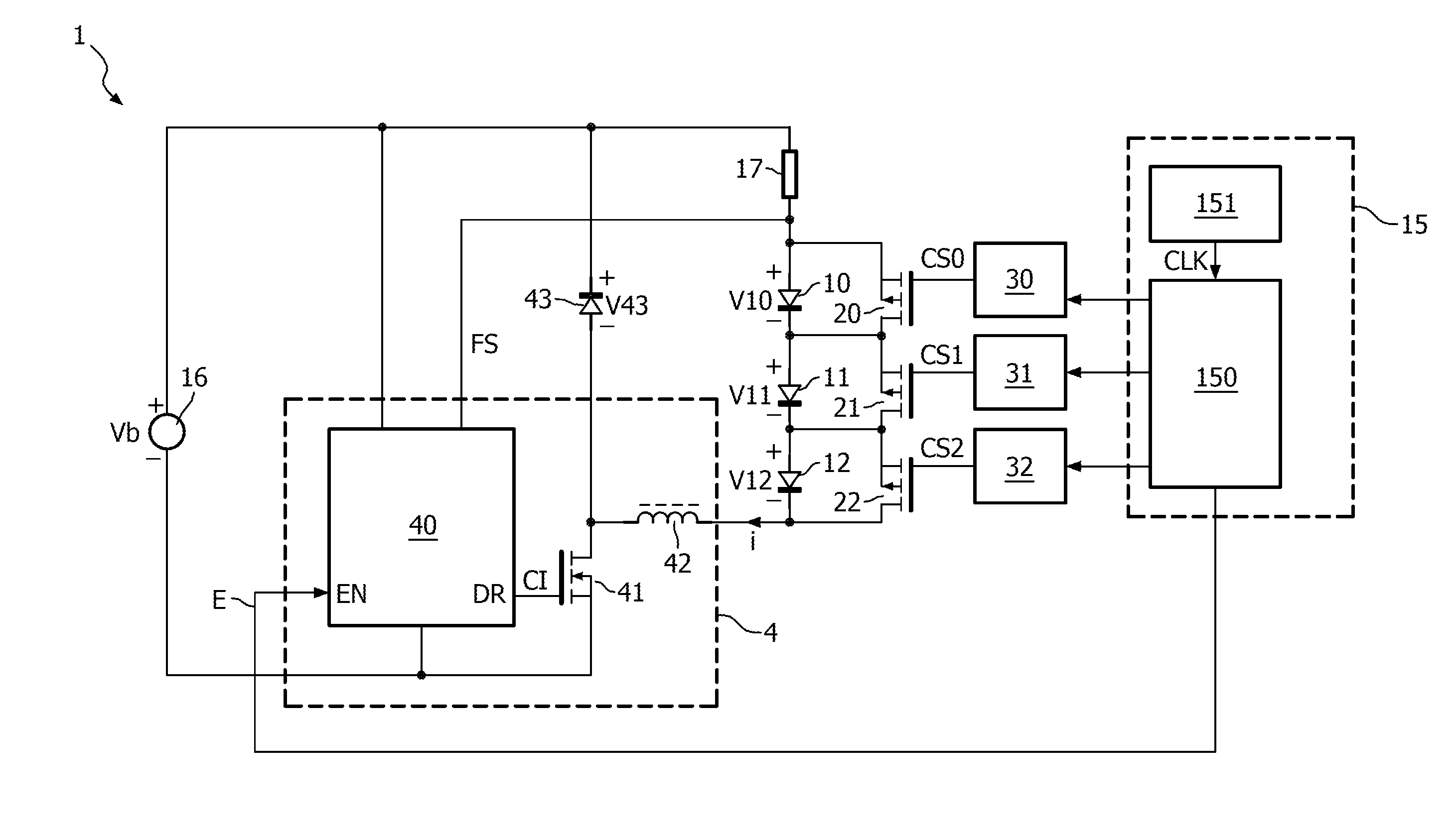
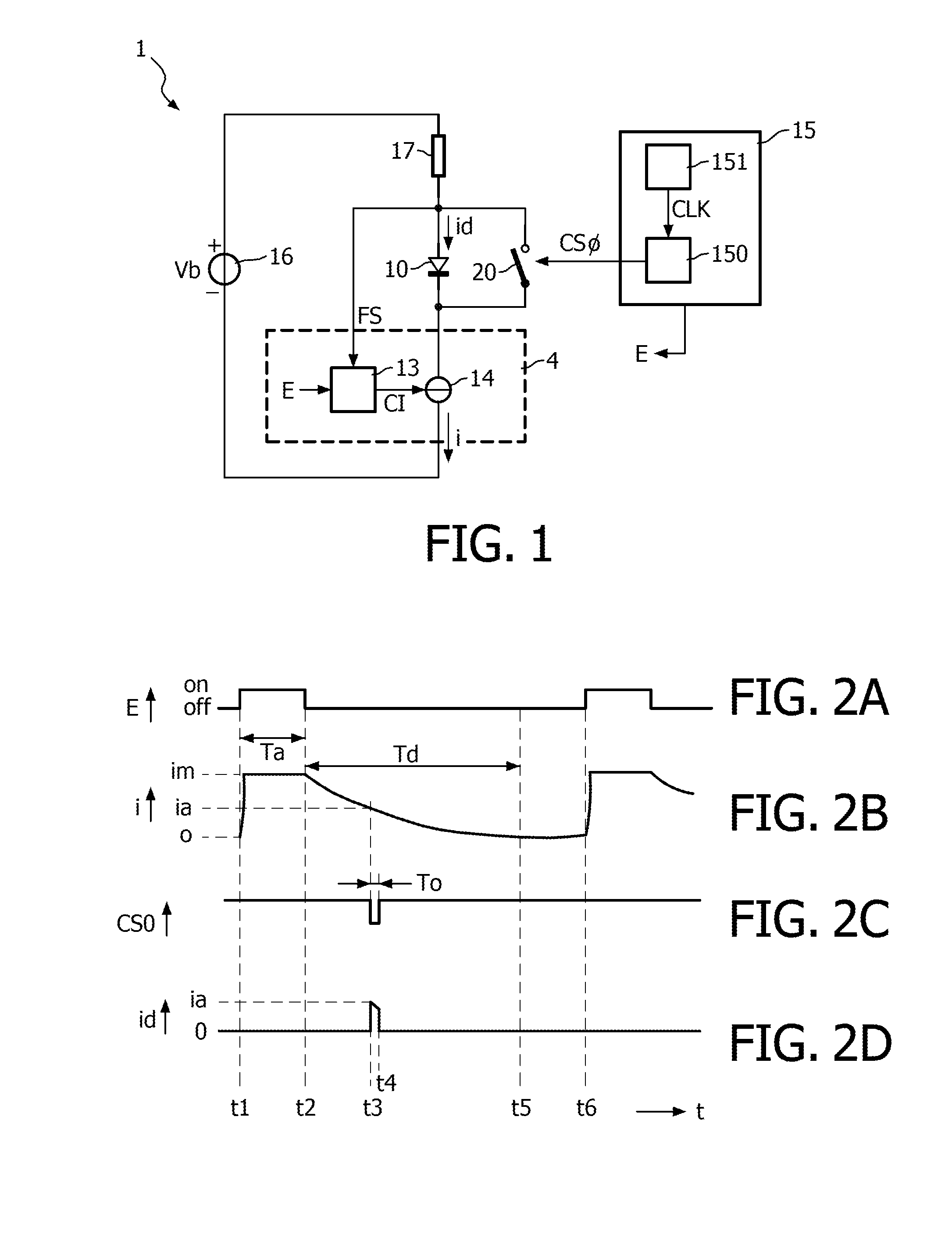
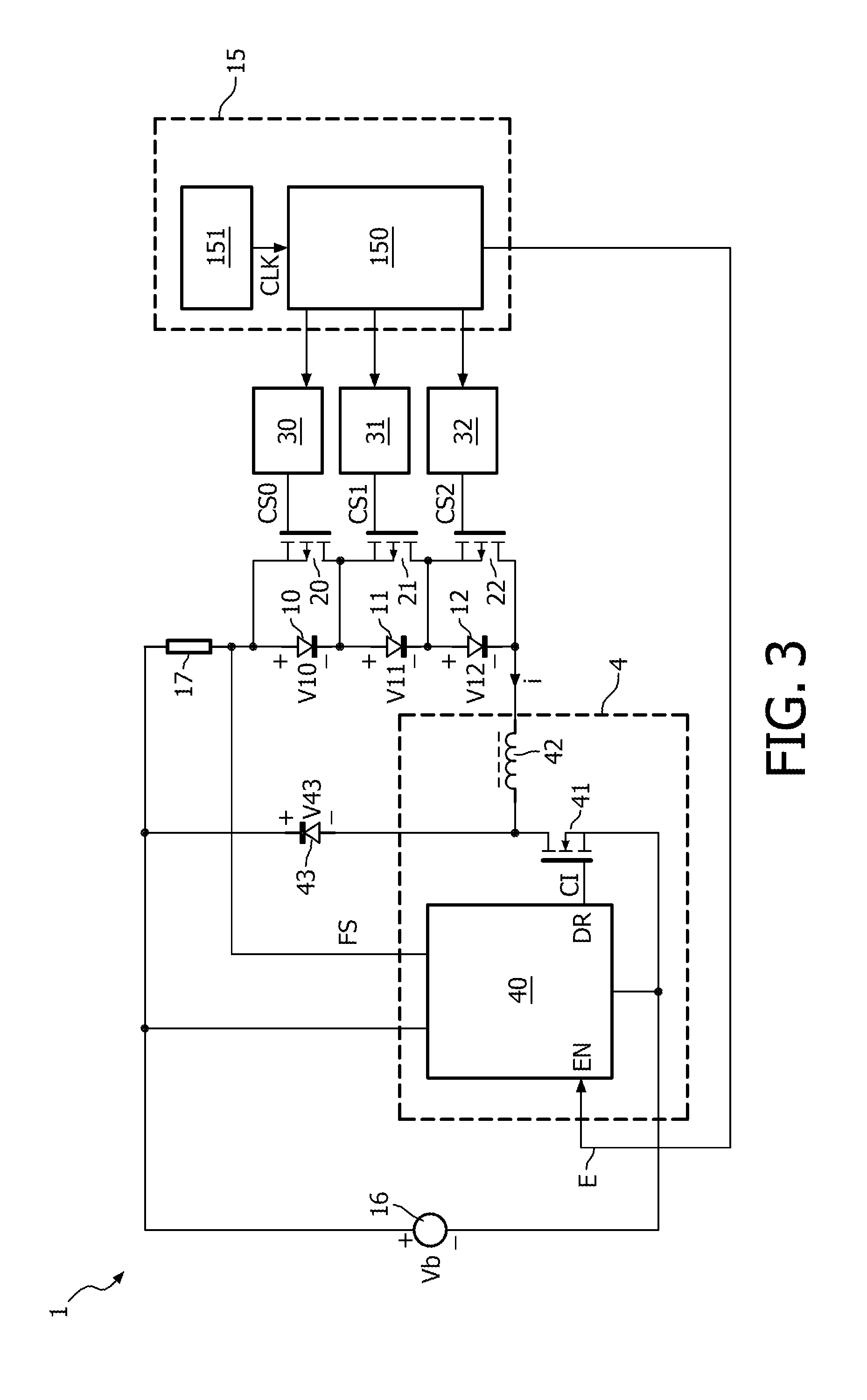
[0027]FIG. 1 schematically shows a lamp 1 including a LED 10 and a controller 15. The voltage source 16 supplies a power supply voltage Vb to a series arrangement of a sensing resistor 17, the LED 10 and the current source 4. The current source 4 comprises the current generator 14 and a controller 13. The controller 13 receives an enable signal E and a feedback signal FS to supply a control signal CI to the current generator 14. The enable signal E is used to activate the current source 14 during the constant current period Ta (see FIG. 2B). When the enable signal E activates the current source 14 it is regulated to supply the non-zero...


PUM


Abstract

A LED driver system (1) comprises a current source (4) which supplies a power supply current (i) to a parallel arrangement of a parallel switch (20) and a LED (10). The parallel switch (20) short-circuits the LED (10) when it is closed. A controller (15) generates during use: (i) a first control signal (E) to control the current source (4) to change from a regulating mode wherein the power supply (i) current is regulated to have a non-zero average level into a decaying mode wherein the power supply current (i) decays during a decay period (Td), and (ii) a second control signal (CSO) to control the parallel switch (20) to open during an open period (To) comprising a sub-period of the decay period (Td).

Description

FIELD OF THE INVENTION[0001]The invention relates to a LED (Light Emitting Diode) driver system, to a lamp comprising such a LED driver system and to method of driving a LED.BACKGROUND OF THE INVENTION[0002]WO 2010 / 128845 discloses a control unit for a LED assembly and a lighting system. A buck converter supplies a power supply current to a series arrangement of LED's. The LED's can be dimmed by switching on and off the buck converter with a particular power supply duty-cycle. Such a power supply duty-cycle dimming (also referred to as PWM control) is applied to all the LED's in the string and thus does not allow to dim the LED's individually. Alternatively, across each one of the LED's an associated LED switch is arranged. Now, the on and off times of the LED switches can be different for different LED's. When the LED switch is open, the current flows through the LED and when the LED switch is closed the current flows through the LED switch. The LED will be dimmed more if the LED s...

Claims


Application Information

Patent Timeline
IPC IPC(8): H05B33/08H05B44/00
CPCH05B33/0824H05B45/48Y02B20/30H05B45/3725H05B44/00H05B45/44
Inventor HEERINGA, SCHELTE
Owner KONINKLIJKE PHILIPS ELECTRONICS NV
Why Eureka
Try Eureka