
Vacuum cleaner with articulated suction port assembly

a vacuum cleaner and suction port technology, applied in the field of vacuum cleaners, can solve the problems that the conventional vacuum cleaner b>100/b> often has difficulty in cleaning crevices or corners of the room, and achieve the effect of efficient cleaning

Inactive Publication Date: 2007-09-25
SAMSUNG GWANGJU ELECTRONICS CO LTD
View PDF16 Cites 57 Cited by
  • Summary
  • Abstract
  • Description
  • Claims
  • Application Information

AI Technical Summary

Benefits of technology

[0009]Accordingly, on object of the present invention is to provide a suction port assembly of a vacuum cleaner, which has an improved articulated portion enabling a higher efficiency cleaning operation and facilitating rotation of the extended flow passage with respect to the suction head.
[0013]Because the extended flow passage is rotatable with respect to the suction head about a plurality of axes, a wide range of cleaning area including crevices and corners can be cleaned efficiently.
[0023]By drawings contaminants in through the side of the suction head in addition to the front, contaminants, even in the crevice and corner areas, can be efficiently cleaned.

Problems solved by technology

For example, the conventional vacuum cleaner 100 often has difficulty in cleaning crevices or corners of a room.

Method used


Image

  • Vacuum cleaner with articulated suction port assembly
  • Vacuum cleaner with articulated suction port assembly
  • Vacuum cleaner with articulated suction port assembly

Examples


Embodiment Construction

[0032]The present invention will be described in greater detail with reference to the accompanying drawings.

[0033]The matters defined in the description, such as a detailed construction and elements, are provided only to assist in a comprehensive understanding of the invention. Thus, it is apparent that the present invention can be carried out without such defined matters. Also, well-known functions or constructions are not described in detail.

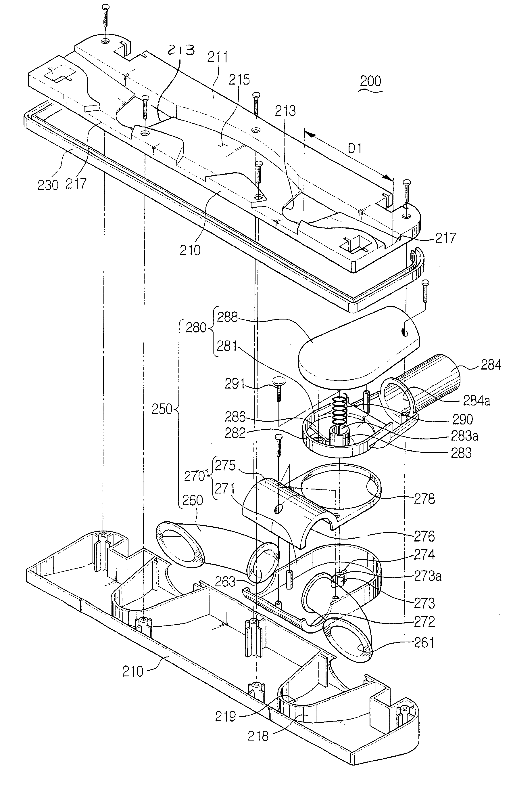
[0034]Referring to FIGS. 3 and 4, a suction port assembly 200 of a vacuum cleaner according to an embodiment of the present invention includes a suction head 210 and an articulated portion 250.

[0035]The suction head 210 draws in dust from a surface being cleaned, and as shown in FIG. 5, includes a pair of spaced suction holes 213, an inner partition 218, a connection recess 215, and a suction groove 217. A member 230 is a bumper which decreases impact of the suction head 210 with obstacles during operation of the vacuum cleaner.

[0036]The pair ...


PUM


Abstract

A suction port assembly of a vacuum cleaner is connected with a cleaner body by an extended flow passage and draws in air and dust from a surface being cleaned when the cleaner is in operation. The suction port assembly includes a suction head having a suction hole formed at a bottom surface opposite to the surface being cleaned. A first connection member extends from one side of the suction head. A second connection member rotatably connects at one end to an exit end of the first connection member and rotates about a first axis to move upwardly and downwardly with respect to the suction head, and at the other end is connected with the extended flow passage. A third connection member engages the second connection member with one end rotatable about a second axis substantially perpendicular to the first axis, and the other end disengageably connected to the extended flow passage.

Description

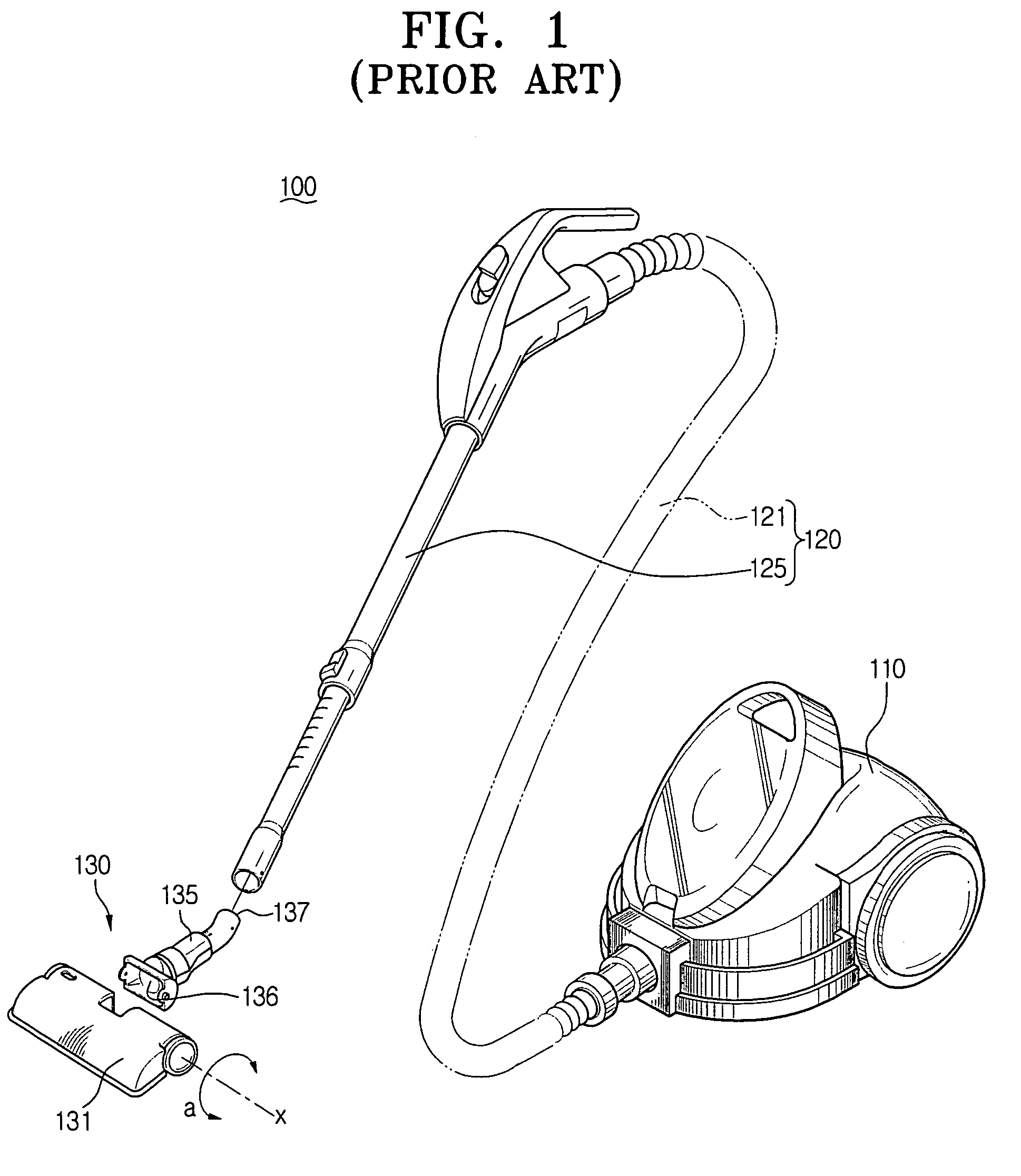
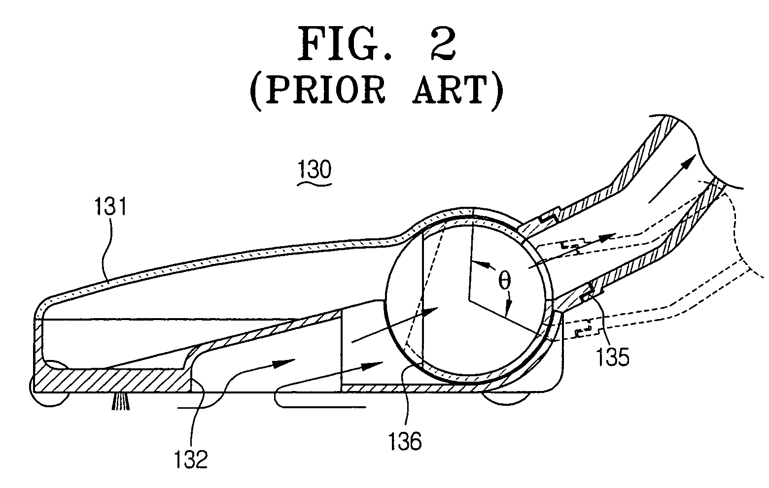
RELATED APPLICATION[0001]This application claims priority to copending Korean Patent Application No. 2004-88200 filed Dec. 5, 2003, in the Korean Intellectual Property Office, which is incorporated herein by reference in its entirety.CROSS-REFERENCE TO RELATED APPLICATION[0002]This application is related to copending application entitled “Suction Brush Assembly Having Rotation Roller Sweeping Dust” (Korean Application No. 2002-11240, filed Mar. 4, 2002).FIELD OF THE INVENTION[0003]The present invention relates to a vacuum cleaner, and more particularly, to a suction assembly of a vacuum cleaner which draws in air and contaminants from a surface being cleaned.BACKGROUND OF THE INVENTION[0004]Conventional vacuum cleaners generally draw in air and dust from a surface being cleaned by utilizing a suction force generated by a vacuum generator of the vacuum cleaner body. Referring to FIG. 1, a general conventional vacuum cleaner 100 comprises a cleaner body 110 housing a vacuum generator ...

Claims


Application Information

Patent Timeline
Patent Type & Authority Patents(United States)
IPC IPC(8): A47L9/02A47L9/24
CPCA47L9/02
Inventor CHOI, KEON-SOO
Owner SAMSUNG GWANGJU ELECTRONICS CO LTD
Learn More