Air gap-insulated exhaust manifold for internal combustion engines

a technology for internal combustion engines and exhaust manifolds, which is applied in the direction of exhaust treatment, machines/engines, mechanical equipment, etc., can solve the problems of high thermal load on the exhaust manifold, increased production and assembly costs, and increased complexity of the exhaust manifold, so as to achieve easy assembly

Inactive Publication Date: 2007-09-25
HEINRICH GILLET GMBH & CO KG
View PDF12 Cites 4 Cited by
  • Summary
  • Abstract
  • Description
  • Claims
  • Application Information

AI Technical Summary

Benefits of technology

[0007]It is the object of the present invention to provide an exhaust manifold of the type indicated above which consists of only a few individual parts and which can be easily assembled in an almost completely automated manner.
[0017]A first essential advantage of the inventive exhaust manifold is that it consists of only five individual parts. Another advantage is that both the inner shell and the outer shell have closed surfaces, which makes them extremely sturdy. In addition, the welds between the lower and upper parts of the inner and outer shells can be positioned in such a way that there is no danger that weld spatters can remain in the exhaust-carrying parts. The mounting surface area of the exhaust manifold on the engine block is minimal. Free spaces to accommodate the fastening screws can be easily formed in the inner and outer shells. Generally, the inventive exhaust manifold is mounted on the engine block in exactly the same way as the current method.

Problems solved by technology

The temperature of these gases subjects the manifold to high thermal loads.
The inner shell thus consists of a plurality of individual parts, which means that both production and assembly become more difficult and more expensive.
This makes the exhaust manifold extremely complicated.
The support cage also reduces the insulating effect of the air gap.
The disadvantage is the reduction in the insulating effect of the air gap caused by the retaining straps and by the large mounting surface on the engine block.

Method used


Image

  • Air gap-insulated exhaust manifold for internal combustion engines
  • Air gap-insulated exhaust manifold for internal combustion engines
  • Air gap-insulated exhaust manifold for internal combustion engines

Examples


Embodiment Construction

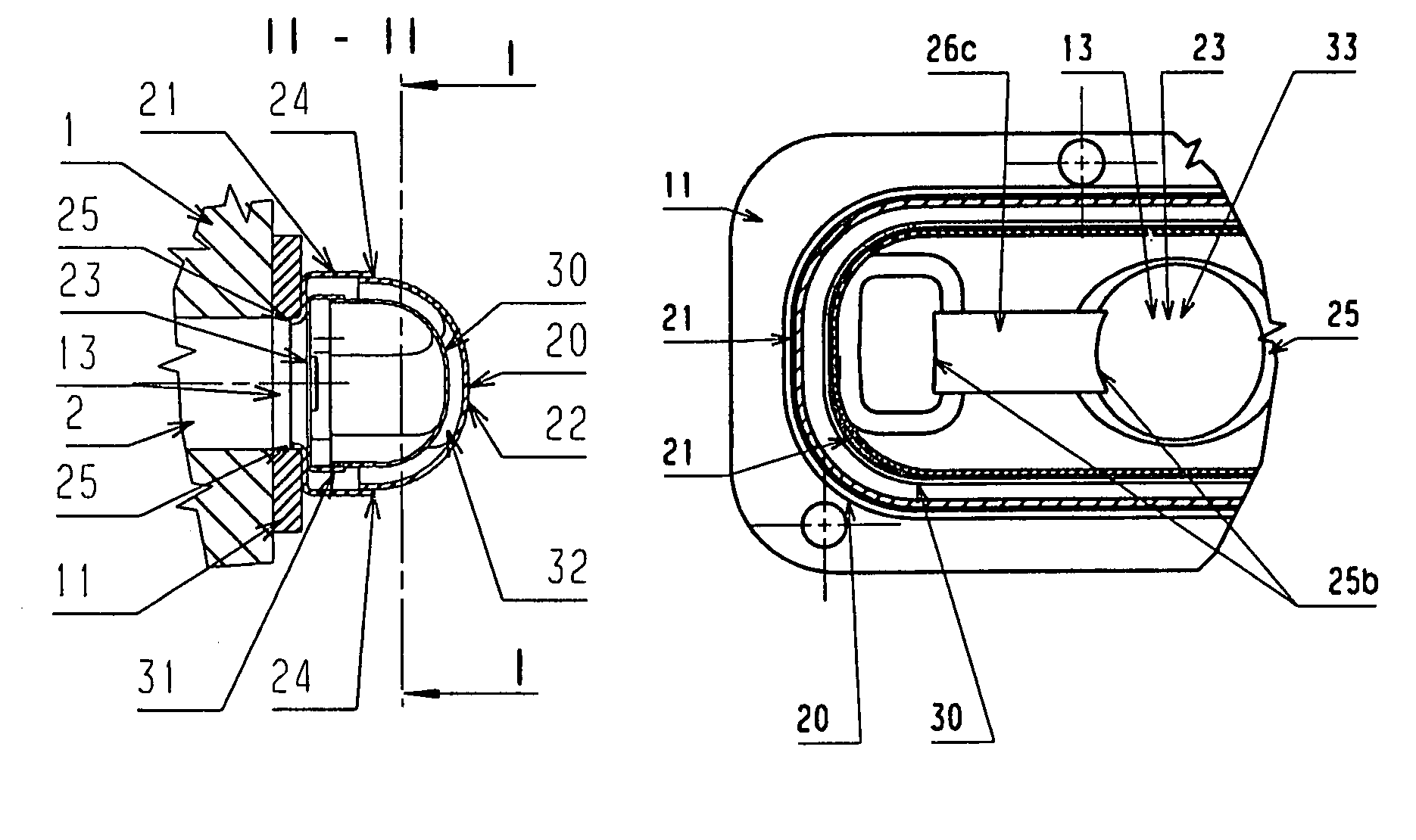
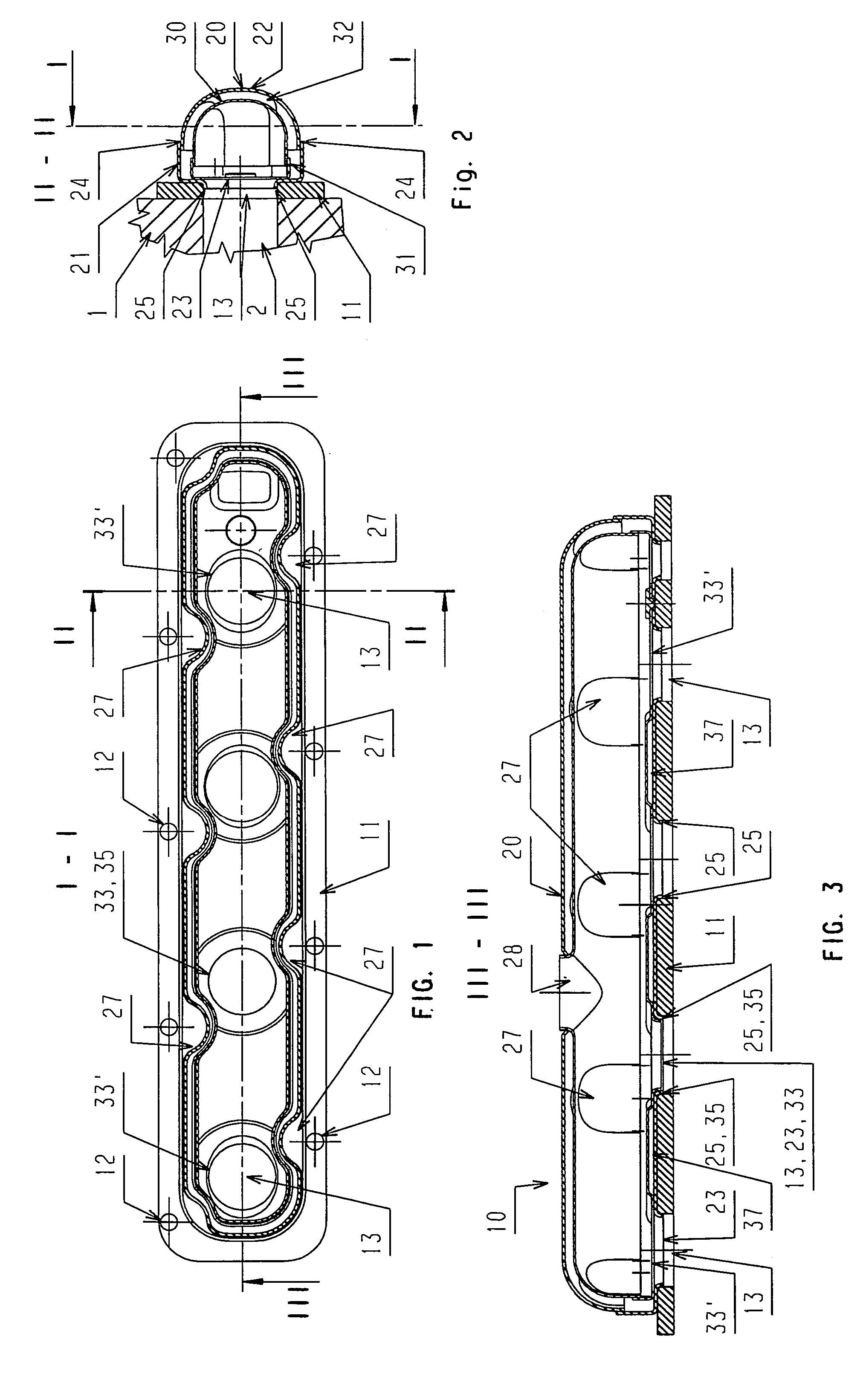
[0028]In the form of three orthogonal cross sections along lines I-I, II-II, and III-III, FIGS. 1-3 show parts of an air gap-insulated exhaust manifold 10 for internal combustion engines.

[0029]The basis of the manifold 10 is a sturdy flange 11 with openings 12 for fastening screws and with gas through-openings 13, which are aligned with the cylinder exhaust ports 2 of the internal combustion engine 1.

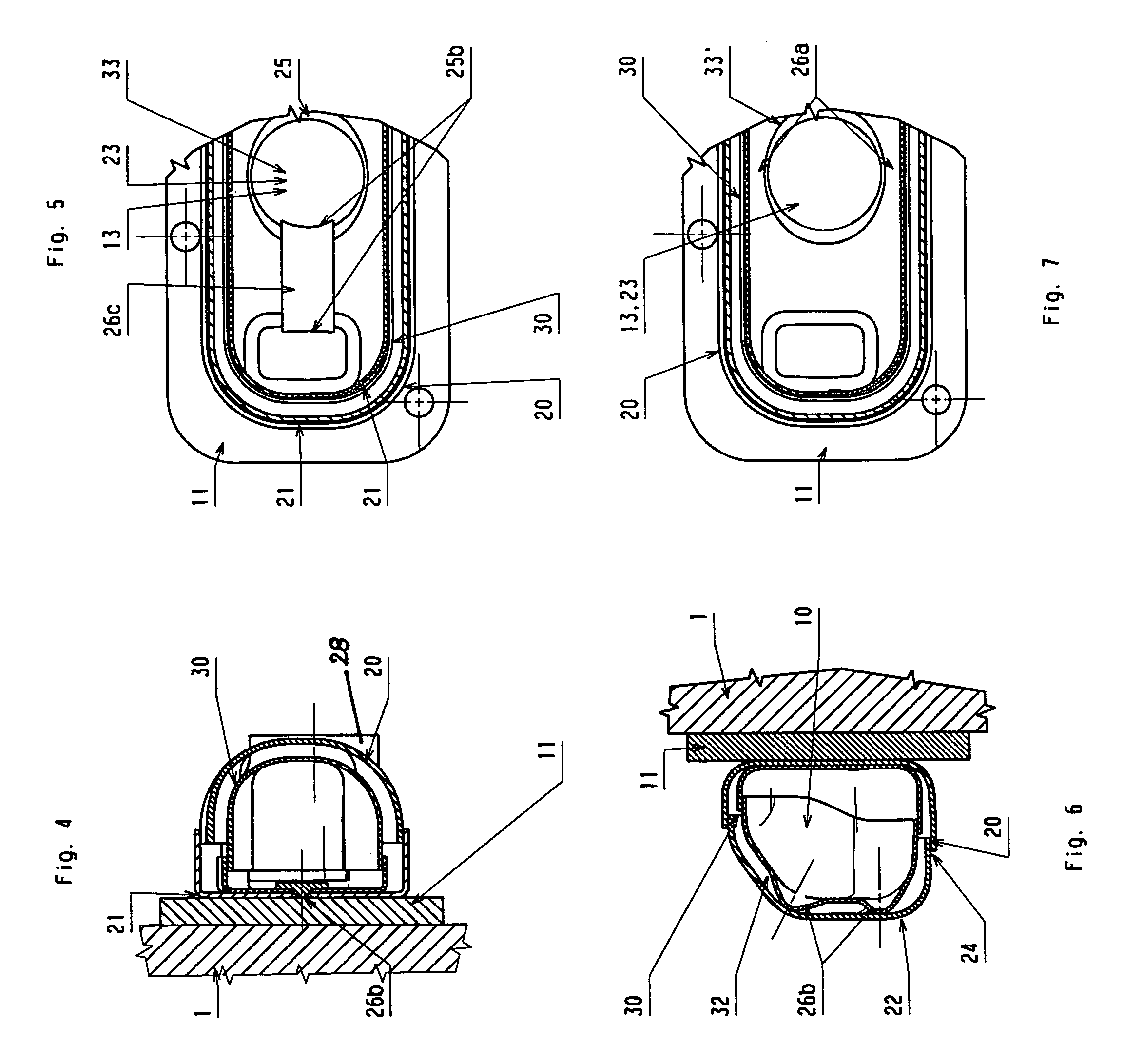
[0030]A trough-shaped lower part 21 of an outer shell 20 is first attached in a gas-tight manner to the flange 11. The lower part 21 has gas through-openings 23, which align with the gas through-openings 13 in the flange 11 and in the cylinder head of the engine. To produce a gas-tight seal, the gas through-openings 13, 23 are provided with circular welds 25. Laser stitch welding is especially suitable for this purpose, because no welding spatters are created.

[0031]An inner shell 30 is placed inside the trough-like lower part 21 of the outer shell 20. The inner shell 30 consists of a tr...


PUM


Abstract

An air gap-insulated exhaust manifold for internal combustion engines. The manifold includes a flange with openings for fastening elements and further openings, which align with the cylinder exhaust ports of the internal combustion engine. A gas-tight outer shell is connected to the flange. An inner shell is provided with openings, which align with the cylinder exhaust ports of the internal combustion engine. The outer shell has a trough-shaped lower part and a hood-shaped upper part, which is welded gas-tight to the lower part. The inner shell has a trough-shaped lower part and a hood-shaped upper part. The outer shell is connected to the flange in a gas-tight manner. The inner shell is firmly attached to the outer shell at only one place.

Description

BACKGROUND OF THE INVENTION[0001]The invention relates to an air gap-insulated exhaust manifold for internal combustion engines.[0002]Exhaust manifolds have the job of collecting the hot exhaust gases emerging from the cylinder exhaust ports of internal combustion engines and of conducting them to the downstream exhaust system components such as catalysts, mufflers, etc. The temperature of these gases subjects the manifold to high thermal loads. In an initial attempt to reduce the amount of heat discharged to the outside, exhaust manifolds were provided with water cooling systems. An example is described in DE 725 013 C1. In the development of this water-cooled exhaust manifold, special value was placed on the ability to compensate for the changes in the length of the various metal parts caused by the different degrees to which they are heated. This goal is achieved by the use of built-in sliding seats. Stuffing-box seals are provided at the points where the muffler brackets pass wi...

Claims


Application Information

Patent Timeline
Patent Type & Authority Patents(United States)
IPC IPC(8): F01N3/00F01N13/08F01N13/10F01N13/14F01N13/18
CPCF01N13/102F01N13/105F01N13/14F01N13/1805F01N13/1838F01N13/1888F01N2260/10F01N2450/22
Inventor GEMINN, MARKUSSTEIGERT, ANDREASROTH, MARGIT
Owner HEINRICH GILLET GMBH & CO KG
Why Eureka
Try Eureka