Variable turbocharger apparatus with bypass

Active Publication Date: 2007-09-25
LEAVESLEY MALCOLM GEORGE
View PDF22 Cites 33 Cited by
  • Summary
  • Abstract
  • Description
  • Claims
  • Application Information

AI Technical Summary

Benefits of technology

[0003]It is an aim of the present invention to

Problems solved by technology

One of the problems with such known variable turbocharger apparatus is the overall range limit, whereby if all of the gases are passed through the turbine, and if the variable t

Method used


Image

  • Variable turbocharger apparatus with bypass
  • Variable turbocharger apparatus with bypass
  • Variable turbocharger apparatus with bypass

Examples


Example

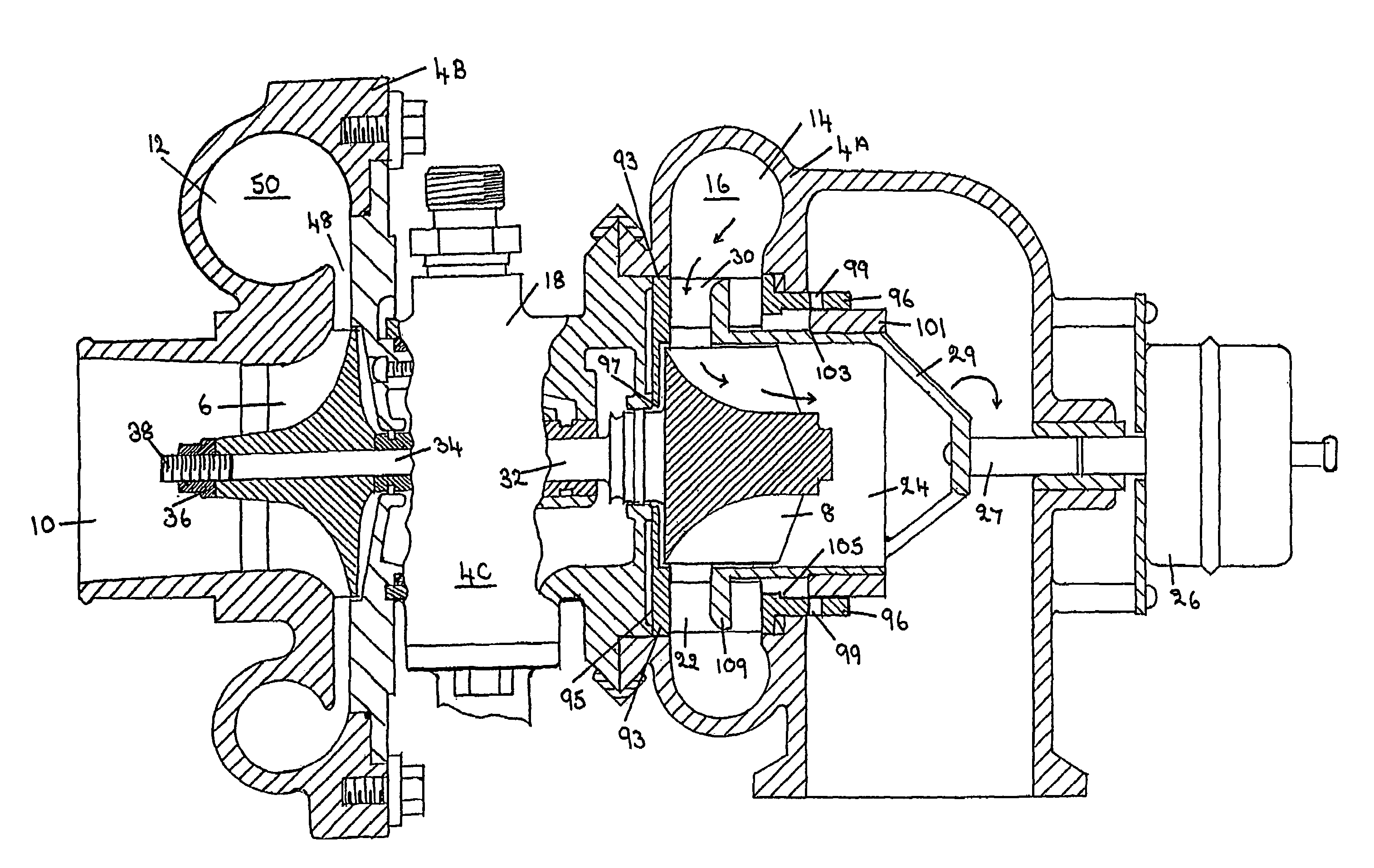
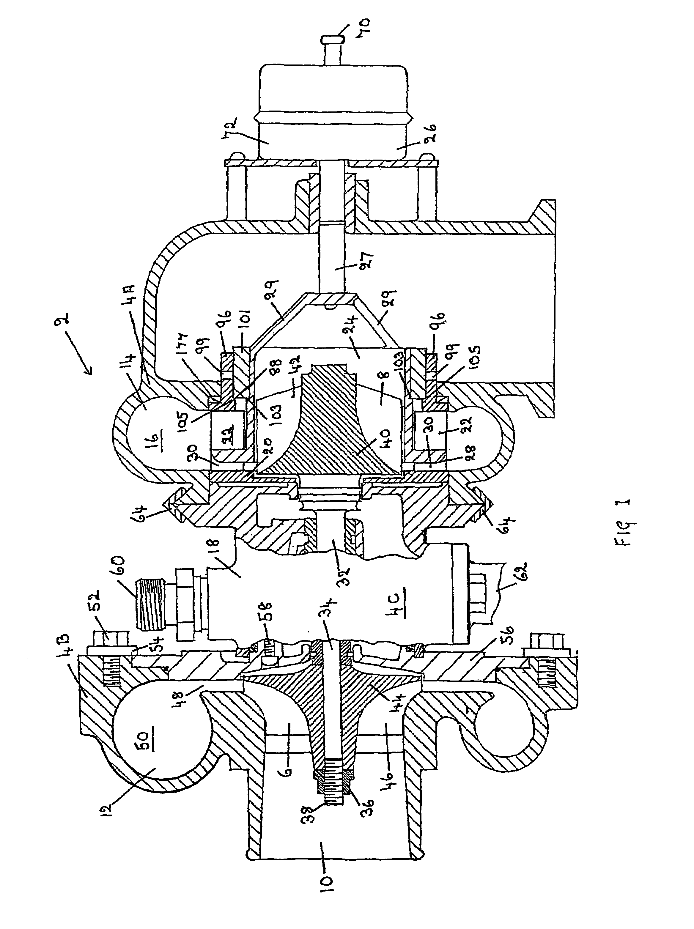
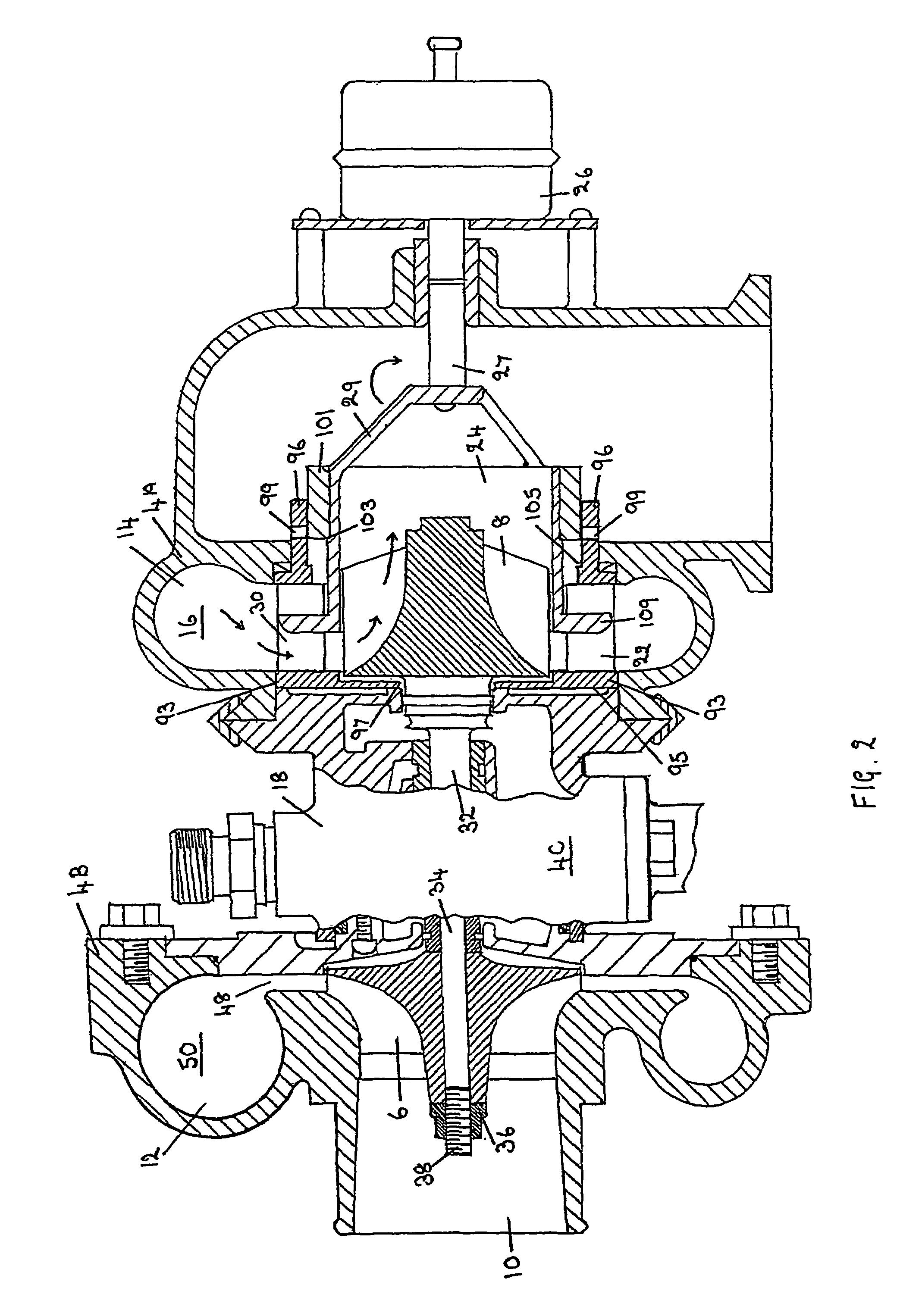
[0043]Referring to FIGS. 1-4, there is shown variable turbocharger apparatus 2 comprising a housing 4 a compressor 6 mounted for rotation in the housing 4, and a turbine 8 which is also mounted for rotation in the housing 4. The variable turbocharger apparatus 2 also comprises a first inlet 10 for enabling air to be conducted to the compressor 6, and an outlet 12 for enabling air from the compressor 6 to be conducted to an engine (not shown).

[0044]The variable turbocharger apparatus 2 has a second inlet 14 for enabling exhaust gases from the engine to be conducted to the turbine 8 in order to rotate the turbine 8. A chamber 16 extends around the turbine 8 and receives the exhaust gases from the second inlet 14 before the exhaust gases are conducted to the turbine 8.

[0045]A bearing assembly 18 permits the rotation of the turbine 8. A heat shield 20 is provided for shielding the bearing assembly 18 from heat from the exhaust gases.

[0046]The variable turbocharger apparatus 2 comprises ...


PUM


Abstract

Variable turbocharger apparatus comprising a housing, a compressor, a turbine, a chamber which extends around the turbine, a bearing assembly for the turbine, vanes mounted in the chamber, a piston positioned between the housing and the turbine, a control device controlling the piston, a piston end nearest the bearing assembly defining a gap, which is variable in size to control exhaust gases acting on the turbine, at least one bypass aperture which opens to allow exhaust gases that are not required for acting on the turbine to bypass the turbine, and sliding of the piston being such that the piston is always maintained in a position which enables the turbine speed to be controlled through the gap alone when there is no bypass and through the gap and the bypass aperture when there is bypass.

Description

BACKGROUND OF THE INVENTION[0001]This invention relates to turbocharger apparatus and, more especially, this invention relates to variable turbocharger apparatus.[0002]Variable turbocharger apparatus is known comprising a housing, a compressor mounted for rotation in the housing, a turbine mounted for rotation in the housing, a first inlet for enabling air to be conducted to the compressor, an outlet for enabling air from the compressor to be conducted to an engine, a second inlet for enabling exhaust gases from the engine to be conducted to the turbine in order to rotate the turbine, a chamber which extends around the turbine and which receives the exhaust gases from the second inlet before the exhaust gases are conducted to the turbine, a bearing assembly for permitting the rotation of the turbine, a heat shield for shielding the bearing assembly from the exhaust gases, and a control system to control the speed of the turbine. One of the problems with such known variable turbochar...

Claims


Application Information

Patent Timeline
IPC IPC(8): F02D23/00F01D17/12F01D17/14F04D25/04F01D17/16
CPCF01D17/167F04D25/04
Inventor LEAVESLEY, MALCOLM GEORGE
Owner LEAVESLEY MALCOLM GEORGE
Why Eureka
Try Eureka