Fluid container with integral brush

a technology of fluid container and brush, which is applied in the direction of writing connector, brush, printing, etc., can solve the problems of difficulty in use and the number of pump actions of the dispenser, and achieve the effect of less likely to tip over and low profil

Inactive Publication Date: 2007-09-25
JONES GARON G
View PDF22 Cites 0 Cited by
  • Summary
  • Abstract
  • Description
  • Claims
  • Application Information

AI Technical Summary

Benefits of technology

[0010]The present invention generally to using a container and brush combination where the brush is insertable inside the container and, when not in use, at least a portion of the brush (e.g., a brush handle) is storable on the container. In keeping with these objects and others, which may become apparent, the present invention uses, in one embodiment, a tire shaped reservoir having a first peripheral surface, a second peripheral surface substantially perpendicular to the first peripheral surface and a third peripheral surface substantially parallel to the first peripheral surface and substantially perpendicular to said second peripheral surface; a handle connected to the first peripheral surface; a stand connected to the second peripheral surface; an applicator handle coupled to the fluid container; and a lid coupled to the fluid container wherein the lid covers an opening to the tire shaped reservoir. In various embodiments, the fluid container closely resembles a generally cylindrical automotive tire. Some embodiments of the invention utilize a “low profile” container having a height substantially less than the width diameter of the container. For example, the tire shaped container has a low profile. One advantage of using a low profile container is that the low profile container has a relatively low center of gravity making the container less likely to tip over.

Problems solved by technology

However, in the Holmes patent, neither the brush nor the container are designed to allow the brush to be inserted within the container and thereby access the fluid within the container.
Most conventional containers used for applying a tire cleaning solution are equipped with a spray dispenser that is troublesome to use.
Such a dispenser takes too many pump actions to spray the tire completely and the slightest wind blows the spray on the vehicle and on the person using the dispenser.
Although such prior art brush / container combinations are known they suffer from several disadvantages, such as for example difficulty in use.

Method used


Image

  • Fluid container with integral brush
  • Fluid container with integral brush
  • Fluid container with integral brush

Examples


Embodiment Construction

[0031]So that the manner in which the above recited features of the invention are attained and can be understood in detail, a more particular description of the invention, briefly summarized above, may be had by reference to the embodiments thereof which are illustrated in the appended drawings.

[0032]It is to be noted, however, that the appended drawings illustrate only typical embodiments of this invention and are therefore not to be considered limiting of its scope, for the invention may admit to other equally effective embodiments.

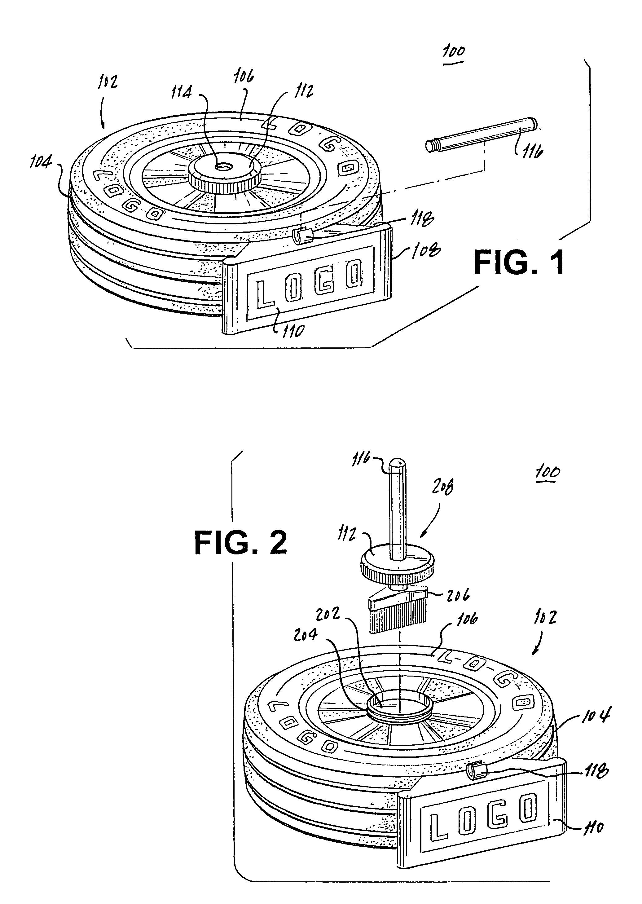
[0033]FIG. 1 depicts a perspective view of an embodiment of a fluid container 100 in accordance with the invention. Specifically, FIG. 1 shows the fluid container 100 illustratively in the shape of a tire 102. The container 100 has a height that is substantially less than its diameter width. Thus the fluid container 100 has a low rise (i.e., a low center of gravity). The low rise of the container 100 allows for a relatively greater stability of the cont...


PUM


Abstract

A fluid receptacle which includes a low profile reservoir having a first peripheral surface, a second peripheral surface substantially perpendicular to the first peripheral surface and a third peripheral surface substantially parallel to the first peripheral surface and substantially perpendicular to the second peripheral surface; a handle connected to the first peripheral surface; a stand connected to the second peripheral surface; an applicator handle coupled to the fluid receptacle; and a lid coupled to the fluid receptacle wherein the lid covers an opening to the tire shaped reservoir. In other embodiments, the low profile fluid reservoir has a tire shape. In yet other embodiments, the receptacle uses a reservoir that does not have a tire shape.

Description

BACKGROUND OF THE INVENTION[0001]1. Field of the Invention[0002]Embodiments of the present invention generally relate to the containment and administration of fluids. More particularly, the invention relates to a container that stores a fluid and an applicator, temporarily located on the container, for the stored fluid.[0003]2. Description of the Related Art[0004]It has been known in the prior art that various liquid products can be packaged and marketed in containers. Similarly, it is known in the prior art, particularly in the prior art pertaining to cleaning products, such as soaps, lotions, etc., that brushes can be provided to be utilized in combination with various types of cleaning products to assist in removing dirt or grime in cooperation with the cleaning fluid, such as soap, etc. These brushes are sold and provided in a wide variety of shapes and sizes. Most of these brushes include structural features mounted on the surface of the body of the brush, such as bristles, to ...

Claims


Application Information

Patent Timeline
Patent Type & Authority Patents(United States)
IPC IPC(8): A46B11/00B43K23/02
CPCA46B11/0006A46B15/0091A46B17/04A46B2200/20
Inventor JONES, GARON G.
Owner JONES GARON G
Why Eureka
Try Eureka