Methods, devices and systems for counterpulsation of blood flow to and from the circulatory system

a technology of blood flow and counterpulsation, which is applied in the direction of blood pump, other medical devices, therapy, etc., can solve the problems of ineffective medication to improve the strength of heart contraction, little progress toward solving this problem on a mass scale, and congestive heart failure, so as to reduce blood clotting

Inactive Publication Date: 2007-09-25
SPENCE PAUL A
View PDF44 Cites 17 Cited by
  • Summary
  • Abstract
  • Description
  • Claims
  • Application Information

AI Technical Summary

Benefits of technology

[0017]The conduit or conduits of the invention may be coupled to a superficial, subcutaneous artery of the patient, such as one or more arteries in the neck, shoulder or upper chest region of the patient. Alternatively, the artery may be located in the retroperitoneal region of the patient, such as the distal aorta, iliac, external iliac, internal iliac or femoral artery systems. The pump may be, for example, implanted in the pelvic region and, more specifically, even in the retroperitoneal region. Although this latter location would be somewhat more invasive than, for example, a superficial region of the chest, it is still much less invasive than intraabdominal or intrathoracic procedures. A direct connection to the aorta may be accomplished with one or more conduits, and with the pump located in the superficial upper chest region similar to a pacemaker. Again, although the connection to the aorta is invasive, the superficial location of the pump makes the overall procedure much less invasive than conventional invasive procedures and less traumatic to the patient.
[0021]A pulsatile counterpulsation pump for use in assisting the heart of a patient, in accordance with the invention, comprises a pump housing having a chamber and an inlet and an outlet in fluid communication with the chamber. A movable member is mounted in the housing and suctions blood into the inlet and expels blood from the outlet in a pulsatile manner. A flushing fluid inlet communicates with the chamber for introducing a flushing fluid into the chamber and reducing blood clotting.

Problems solved by technology

Congestive heart failure is a major problem in today—over 5 million patients in the U.S. and probably even more in the EU are afflicted.
There is no effective medication to improve the strength of heart contraction and to date there has been little advancement toward solving this problem on a mass scale.
Movement is extremely limited as movement on the catheter may cause bleeding from the artery which has been punctured.
Patients often deteriorate while supine as muscles weaken from inactivity and the risk of pneumonia and leg clots increases.
The catheter may be close to the size of the patients groin artery and may occlude the flow of blood to the leg and risking the loss of that limb.
After a number of days there is an increasing risk of leg ischemia and leg loss.
If it is left more than about a week, the doctors become extremely concerned that a serious complication will occur and typically remove the balloon.
Despite the fact that counterpulsation is extremely helpful to these patients, there has been no way to apply this technology practically for a long period of time (i.e., months or years).
Furthermore, these patients are very ill and cannot tolerate major procedures.
However, it is unlikely that this procedure could ever be used on a large scale as it is so invasive.
However, there are a number of problems that have not been satisfactorily solved and this technology is not yet widely used in heart failure.
The first problem is that insertion of these devices requires a major procedure for connection to the heart and the aorta.
The pumps have blood contacting surfaces, particularly bearings, and these are prone to clotting.
Clots may either break loose and embolize (migrate) to the body causing strokes or other organ problems or may stay in place and enlarge to the point that they cause the device to malfunction.
These valves, in combination with stasis points within the system may also contribute to clotting.
Another major problem with these devices is that they require major regulation.
If too little is pumped, the patient suffers from insufficient circulation.
If the pump is set too high, the heart can be sucked flat and then drawn into the pump with serious consequences to the heart.
If the pump does not precisely respond to these variations, failure may occur.
Unfortunately, no chronic form has been developed that can be provided to the patient in a minor procedure, allows mobility and reduces the risk of long term infection.

Method used


Image

  • Methods, devices and systems for counterpulsation of blood flow to and from the circulatory system
  • Methods, devices and systems for counterpulsation of blood flow to and from the circulatory system
  • Methods, devices and systems for counterpulsation of blood flow to and from the circulatory system

Examples


Embodiment Construction

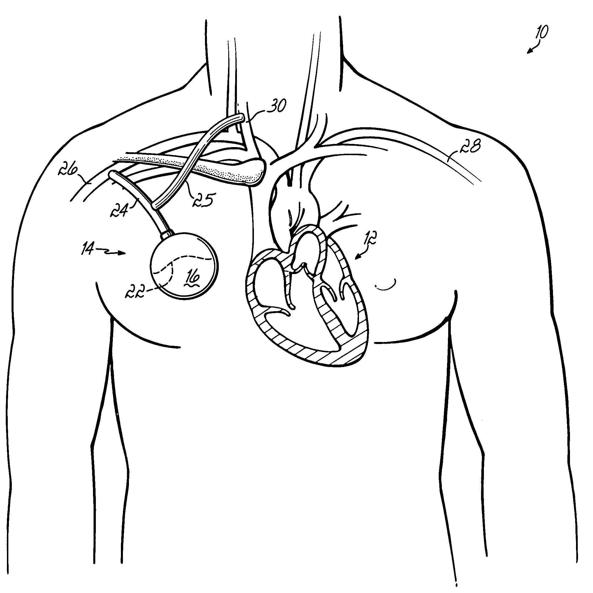
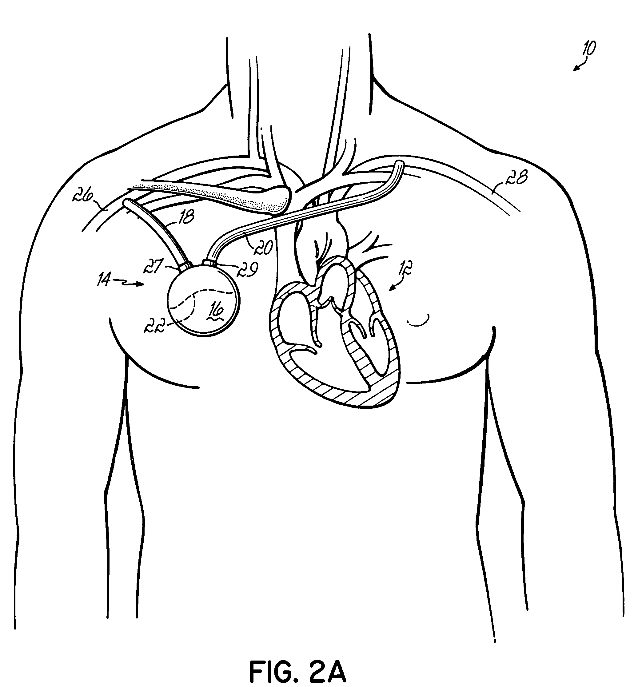
[0038]In each of the systems described below, blood is removed from the patient's arterial blood system during systole and pumped back into the blood system during diastole. In the various figures, like reference numerals refer to like structure, while like reference numerals with prime marks (′) refer to corresponding elements that have been modified in manners that will be apparent or described.

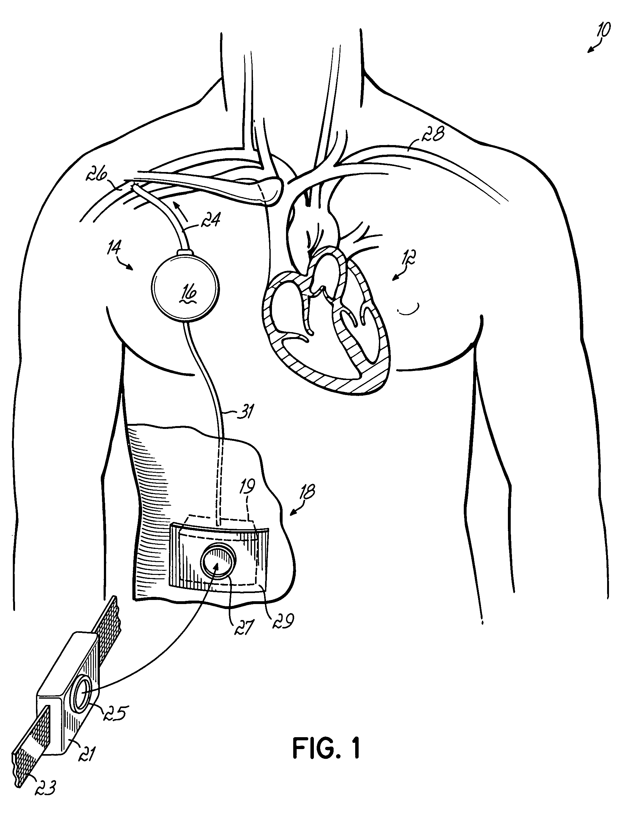
[0039]FIG. 1 illustrates a patient 10 having a heart 12, shown in longitudinal cross section, coupled with a supplemental assist device or system 14. System 14 comprises a pulsatile pump device 16 which may be implanted in a small pocket made subcutaneously over the patient's chest, such as in the subclavicular region as shown in the drawing. This is a similar implantation procedure to conventional pacemakers. Pump 16 is coupled with a control. Power supply 18 may be an implanted power supply or a power supply partially or wholly external to the patient. One particularly desirable power sys...


PUM


Abstract

Counterpulsation methods and systems for assisting the heart of a patient involve, for example, coordinating the operation of a pulsatile pump to suction blood from an artery through a first conduit while the heart is in systole and expel the blood into the first conduit and the artery while the heart is in diastole.

Description

[0001]This application claims the benefit of U.S. Provisional Application No. 60 / 516,529 filed on Oct. 31, 2003, the disclosure of which is hereby incorporated by reference herein.BACKGROUND OF THE INVENTION[0002]Congestive heart failure is a major problem in today—over 5 million patients in the U.S. and probably even more in the EU are afflicted. There is no effective medication to improve the strength of heart contraction and to date there has been little advancement toward solving this problem on a mass scale. Attempts should be directed to a simple, proven and minimally invasive system to help these patients.[0003]Aortic counterpulsation is a well-established form of assistance for a failing heart. In one type of counterpulsation procedure, as the heart ejects blood in systole, blood is removed from the aorta thus relieving the work of the heart in ejecting blood. As the heart relaxes in diastole, the removed blood is pumped back into the aorta increasing the blood pressure and ...

Claims


Application Information

Patent Timeline
Patent Type & Authority Patents(United States)
IPC IPC(8): A61M1/12A61M60/152A61M60/268A61M60/274A61M60/432A61M60/462A61M60/562A61M60/873A61N1/362
CPCA61M1/106A61M1/107A61M1/127A61M1/1044A61M1/1008A61M1/122A61M1/1086A61M1/1005A61M2205/8243A61M60/869A61M60/274A61M60/562A61M60/432A61M60/152A61M60/462A61M60/873A61M60/148
Inventor SPENCE, PAUL A.
Owner SPENCE PAUL A
Why Eureka
Try Eureka