Vortex transducer

a vortex transducer and transducer technology, applied in the field of ultrasonic transducers, can solve the problems of inability to visualize the lesions formed, extended time required, and very slow development of hifu commercialization, and achieve the effect of reliable aiming of a vortex transducer, cheap and cost effective manufacturing process

Inactive Publication Date: 2007-09-25
LIPOSONIX
View PDF74 Cites 171 Cited by
  • Summary
  • Abstract
  • Description
  • Claims
  • Application Information

AI Technical Summary

Benefits of technology

[0026]It is still further an objective of the present invention to be able to reliably aim a vortex transducer without using a lens or electronic steering.
[0027]Yet another objective is to provide for a vortex transducer with a cheap and cost effective manufacturing process.

Problems solved by technology

HIFU commercialization has been very slow to develop, however, despite some of its early promise.
Reasons for this include the inability to visualize the lesions being formed, the necessity of having to lyse an entire malignant tumor to be considered effective, and especially the extended period of time required to lyse a significant volume of tissue.
Advances in the treatment of BPH with drugs, however, has seriously shrunk the commercial prospects for this case.
Preferred thermal processes are generally slow, so that it may take up to 30 seconds to generate enough absorption of the ultrasonic energy to raise the temperature high enough to necrose tissue, and additional time to allow the temperature of tissue between the skin and treated volume to cool sufficiently before the next lesion is created.
While some combination of these strategies could be employed, a major physical limitation of reducing scanning time remains the small diameter of the focused ultrasound beam.
This research has shown that challenges remain in reducing the overall treatment time to the desired values.
At very high power levels, or too long insonification times, excessive heat can be generated above the focal zone which will lyse tissue up to and including the skin surface.
While large volumes of tissue can be lysed in this manner, controlling this type of lesion growth can be problematic when considering patient and environmental variability.
However, flexible composites are inherently high loss materials and unsuitable to the high power levels used in HIFU.
Flexible materials would distort and ultimately disintegrate due to the heat build-up inside the material itself under high drive levels.
Using less flexible polymers as composite filler materials would increase the composites' power handling capabilities due to lower intrinsic loss mechanisms, but would then make forming the composite into a curved shape seemingly impossible.
The epoxy filler then will fully cure, and further heat treatment can elevate the epoxy glass transition temperature, the temperature at which the polymer suddenly will soften, to levels between 120° and 200° C. The material thus formed is relatively low loss and capable of handling HIFU power levels, albeit with less efficiency than solid, high power, piezoelectric ceramics.
However sector-vortex designs require complex electronics to drive the transducers in order to produce the vortex focal field.

Method used


Image

  • Vortex transducer
  • Vortex transducer
  • Vortex transducer

Examples


Embodiment Construction

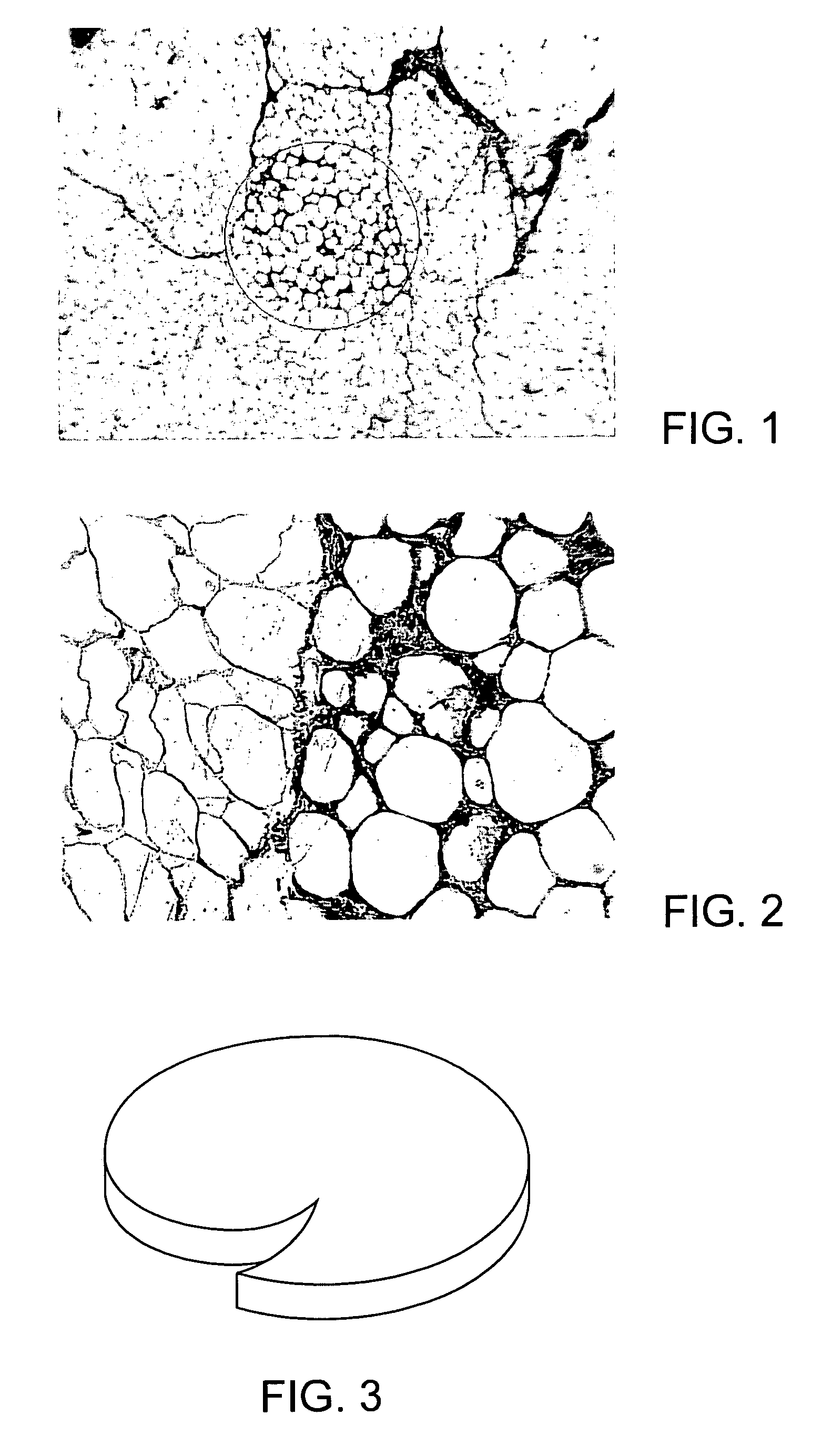
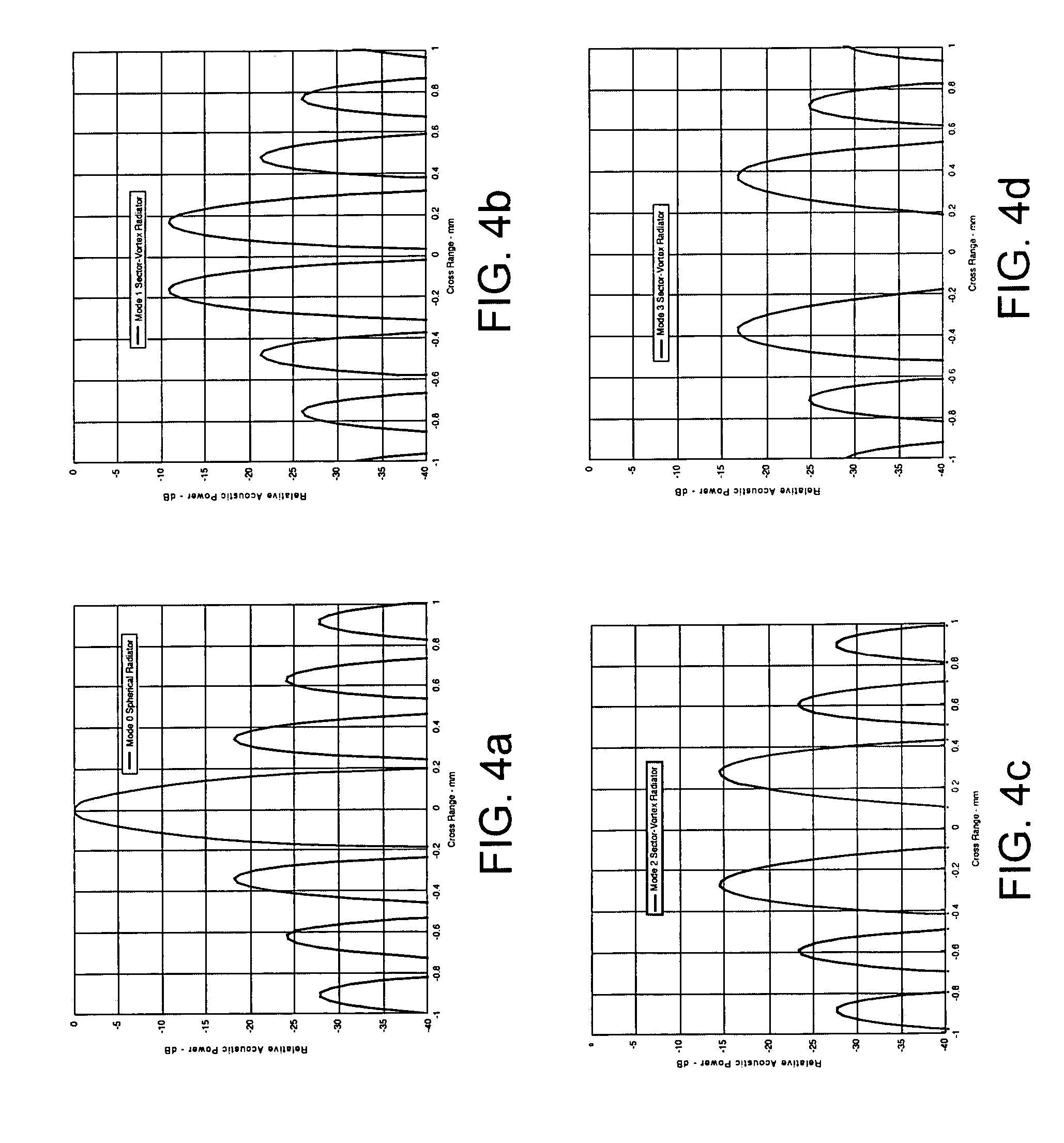
[0038]Described herein is an implementation of a version of the sector-vortex concept. While this concept is known, this disclosure implements the design in a novel manner. In order to avoid the complexities and cost of an electronic beamformer, or the use of a sector-vortex lens with its attendant issues in reliability, acoustic losses and reverberations, and cooling, a continuous vortex lens can be incorporated into the piezoelectric transducer material itself. This can be done by building the transducer out of piezoelectric composite material which can be molded into a vortex lens. This eliminates the need for complex driving electronics and all the issues of an external lens. This design could be instrumental in building cheap, reliable devices that can potentially reduce treatment time by factors of two to eight.

[0039]The present invention implements an applicator design that incorporates the phase shifts mechanically, not electronically. This is mathematically equivalent to le...


PUM


Abstract

A mechanically formed vortex transducer is described. The transducer has a plurality of piezoelectric elements suspended in an epoxy and heat molded into a desired shape. An irregularity in the transducer shape provides for a mechanically induced vortex focal field without the need for electronic steering or lens focusing. A system and methods of making the same are also described.

Description

CROSS-REFERENCES TO RELATED APPLICATIONS [0001]The present application claims the benefit of Provisional Application No. 60 / 459,355, filed Mar. 31, 2003, and of Provisional Application No. 60 / 483,317, filed on Jun. 26, 2003, the full disclosures of which are incorporated herein by reference.BACKGROUND OF THE INVENTION [0002]1. Field of the Invention[0003]The present invention relates to an ultrasound transducer for the use in high intensity focused ultrasound (HIFU) applications for medical applications.[0004]2. Description of the Background Art[0005]Lysis (the process of disintegration or dissolution) of human tissue using high intensity focused ultrasound (HIFU) is a technique that has been studied for over 50 years. Research into applications of HIFU have revolved mostly around treating malignant tumors in the body either untreatable by other means, or promising a more efficacious treatment modality. HIFU commercialization has been very slow to develop, however, despite some of i...

Claims


Application Information

Patent Timeline
Patent Type & Authority Patents(United States)
IPC IPC(8): A61B8/02A61BA61B5/00A61B8/00A61B8/12A61B8/14A61B17/20A61B17/225A61H1/00A61H1/02A61N7/02H01L41/08
CPCA61B8/00A61N7/02A61N2007/0008
Inventor DESILETS, CHARLES S.QUISTGAARD, JENS U.
Owner LIPOSONIX
Why Eureka
Try Eureka