Reactor having a heat exchange medium circulation

a technology of heat exchange medium and reactor, which is applied in the field of reactors, can solve the problems of complex reactor adaptation and the inability to realize the technology of the vertical pump shaft mounted and driven at the lower end, and achieve the effects of novel design, compact design and simple design

Active Publication Date: 2007-09-25
BASF AG
View PDF12 Cites 2 Cited by
  • Summary
  • Abstract
  • Description
  • Claims
  • Application Information

AI Technical Summary

Benefits of technology

[0038]The novel reactor thus has the advantage of ensuring, in a manner which is simple in design, transport of the heat exchange medium stream downward in the pump and hence feeding thereof directly into the upper ring line of a reactor. In the case of the likewise preferred passage of the reaction mixture, downward through the catalyst tubes, the advantageous cocurrent flow of the reaction mixture and heat exchange medium is thus achieved.
[0039]It is particularly advantageous that, owing to the novel design of the pump, the heat exchange medium is close to or at atmospheric pressure at the shaft lead-through from the pump casing into the atmosphere and that there is therefore no need for any packing on the pump shaft at this point.
[0040]Because the feed member is designed as a diagonal rotor, the heat exchange medium is transported directly into the upper ring line of the reactor. A particularly compact design and shorter shaft length compared with known designs with axial-flow feed pumps are thus possible.
[0041]Compared with known designs, the pump shaft is shorter, in particular because of the geometrically favorable transport direction of the diagonal rotor directly into the upper ring li

Problems solved by technology

A pump arrangement having a vertical pump shaft which is mounted and driven at its lower end has not been realized technically to date, in particular owing to the complicated pump shaft packing required in this case.
However,

Method used


Image

  • Reactor having a heat exchange medium circulation
  • Reactor having a heat exchange medium circulation
  • Reactor having a heat exchange medium circulation

Examples


Embodiment Construction

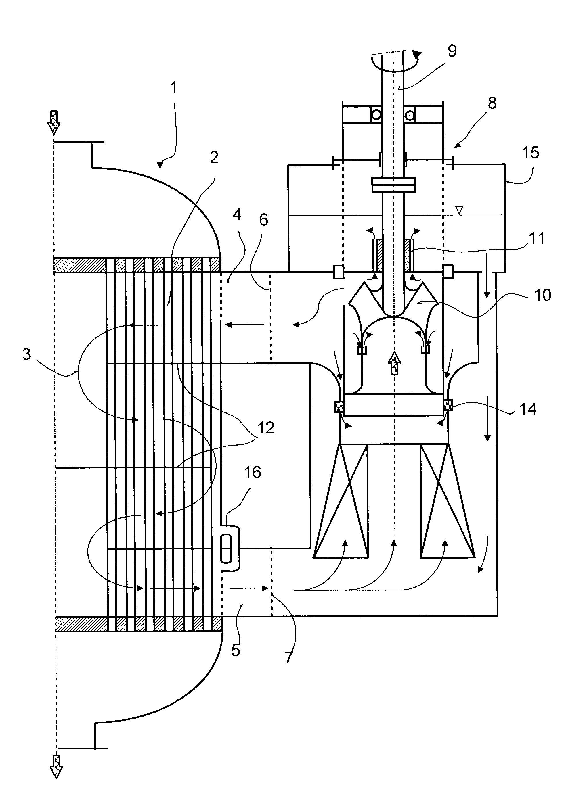
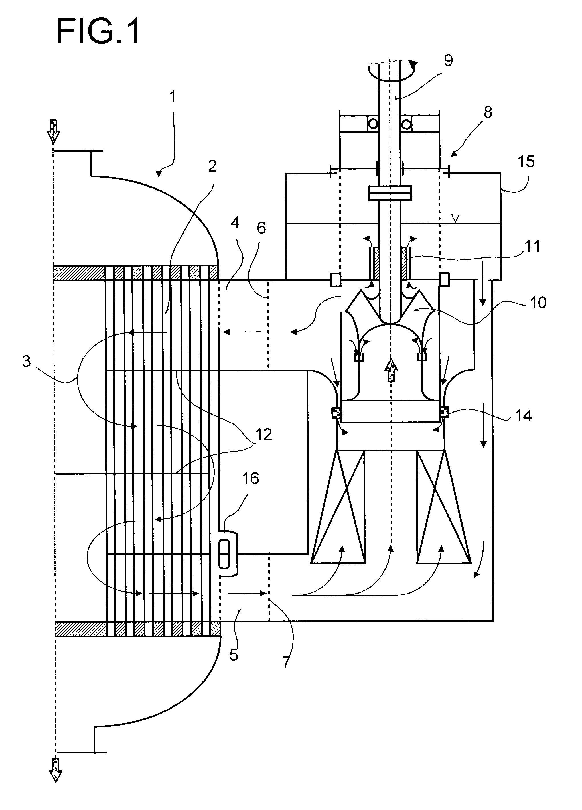
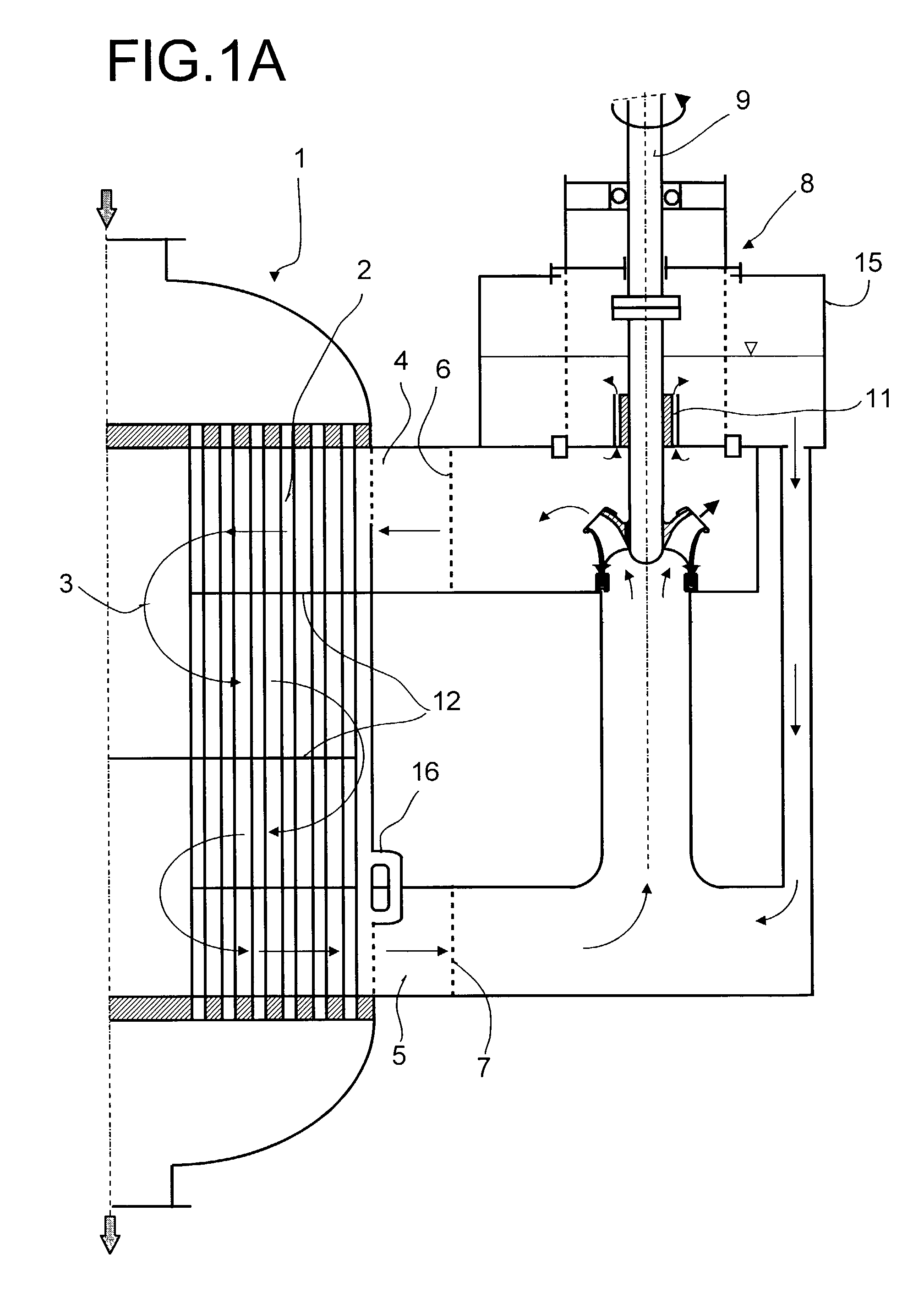
[0051]The longitudinal sectional view in FIG. 1 shows a reactor 1, comprising a bundle of catalyst tubes 2, comprising a heat exchange medium stream 3 through the space between the catalyst tubes, comprising upper ring line 4 and lower ring line 5, in each case with jacket orifices 6 and 7, respectively, and preferably comprising baffle plates 12. The circulation of the heat exchange medium 3 is effected by means of a pump 8 having a pump casing 15 and having a pump shaft 9 on which a diagonal rotor 10 is arranged and which has a leak-permeable restrictor gap 11, in the longitudinal direction of the pump shaft 9, on the pressure side of the pump 8, and preferably a further hydrodynamic bearing 13 (see FIG. 4), which is likewise in the form of a leak-permeable packing lubricated by means of heat exchange medium. The pump 8 is preferably in the form of a slide-in module, and a slide-in bearing 14 is therefore provided which is preferably sealed by a fit, seals the mutually displaceabl...


PUM

PropertyMeasurementUnit
Fractionaaaaaaaaaa
Fractionaaaaaaaaaa
Fractionaaaaaaaaaa

Abstract

A reactor including a bundle of catalyst tubes through which a reaction mixture is passed, and wherein a heat exchange medium is passed through a space surrounding the catalyst tubes and including ring lines at both reactor ends with jacket orifices for feeding in and removing the heat exchange medium by at least one pump. The heat exchange medium is fed to the upper ring line and is sucked in via the lower ring line by the at least one pump having at least one vertical pump shaft mounted and operated at its upper end. The at least one pump includes a diagonal rotor and a restrictor gap in the longitudinal direction of the at least one pump shaft, within the heat exchange medium, on the pressure side of the at least one pump for sealing and mounting the at least one pump shaft and reducing axial shear of the diagonal rotor.

Description

BACKGROUND OF THE INVENTION[0001]1. Field of the Invention[0002]The present invention relates to a reactor comprising a bundle of catalyst tubes, through whose space surrounding the catalyst tubes a heat exchange medium is passed, a pump for circulating the heat exchange medium for a reactor and a use.[0003]2. Discussion of the Background[0004]The conventional design of reactors of the generic type consists of a generally cylindrical container in which a bundle, i.e. a plurality of catalyst tubes is accommodated in a usually vertical arrangement. These catalyst tubes, which, if required, may contain supported catalysts, are tightly fastened at their ends in tube sheets and open in each case into a hood connected at the upper or lower end to the container. The reaction mixture flowing through the catalyst tubes is fed in and removed, respectively, via these hoods. A heat exchange medium circulation is passed through the space surrounding the catalyst tubes, in order to compensate the...

Claims


Application Information

Patent Timeline
IPC IPC(8): F28D21/00F28F13/06B32B27/04F28D15/00F04D29/08B01J8/06B01J19/00B01J19/24C07C27/14C07C45/35C07C47/22C07C51/25C07C57/05C07C59/153C07D307/60C07D307/89F04D7/06F04D11/00F04D29/04F04D29/047F28F27/02
CPCB01J8/067B01J19/0013B01J19/2425C07C45/35F04D7/06F04D29/047F28F27/02C07C47/22B01J2208/00221B01J2219/00076B01J2219/00094B01J2219/00777Y10S165/228
Inventor OLBERT, GERHARDCORR, FRANZ
Owner BASF AG
Why Eureka
Try Eureka