Flexible interconnect structures for electrical devices and light sources incorporating the same

a technology of flexible interconnect structure and electrical device, which is applied in the direction of lighting and heating apparatus, semiconductor/solid-state device details, domestic cooling apparatus, etc., can solve the problems of reducing device life, degrading performance, and excessive junction temperature, and achieves rapid heat dissipation

Inactive Publication Date: 2007-09-25
GENERAL ELECTRIC CO
View PDF18 Cites 46 Cited by
  • Summary
  • Abstract
  • Description
  • Claims
  • Application Information

AI Technical Summary

Benefits of technology

[0007]A flexible interconnect structure comprises a flexible dielectric film having at least a first surface and a second surface and circuit traces being disposed on at least one of the film surfaces. In addition, one or more electrical circuit components can be disposed on a surface of the dielectric film and connected to at least a circuit trace to form an electrical circuit. Portions of the flexible dielectric film are removed through the thickness of the film. Flexible interconnect structures of the present invention allow for rapid dissipation of heat generated during the fabrication or use of electrical devices which comprise such flexible interconnect structures.
[0010]In still another aspect of the present invention, a method is provided for making a flexible interconnect structure that allows for a dissipation of heat generated during a fabrication or use of electrical devices which comprise such flexible interconnect structures. The method comprises: (1) providing a flexible dielectric film having a first surface and a second surface; (2) disposing electrical circuit components and circuit traces on at least one of said surfaces; and (3) removing at least a portion of said film through a thickness thereof, said portion being devoid of said circuit components and said circuit traces.

Problems solved by technology

The waste heat results in excessive junction temperatures, degrading performance and reducing device life.
LED lamps exhibit substantial light output sensitivity to temperature, and can be permanently degraded by excessive temperature.
For example, the maximum recommended operating temperature for LEDs that incorporate indium in their compositions is between about 85° C. and about 100° C. These devices can exhibit typical (half brightness) lives on the order of 50,000 to 100,000 hours at 25° C. However, degradation above 90° C. is rapid as the LEDs degrade exponentially with increases in temperature.
Permanent thermal degradation of LEDs may also occur during array fabrication if care is not taken, when the LEDs are soldered to the supporting and / or interconnecting circuit board.
For example, typical soldering temperatures can exceed 250° C. and seriously affect the performance of the LEDs even before they are put into service, if the LEDs remain at or near such high temperatures for an extended period of time.
However, the formation of such vias adds to the cost of manufacturing the pcb.
In addition, the rate of heat dissipation is limited by the rate of heat conduction through the vias because of their typical small cross section.
These substrates often are costly or require complicated multi-step manufacturing processes.
Thus, a compromise must be accepted which often results in a less efficient overall device.

Method used


Image

  • Flexible interconnect structures for electrical devices and light sources incorporating the same
  • Flexible interconnect structures for electrical devices and light sources incorporating the same
  • Flexible interconnect structures for electrical devices and light sources incorporating the same

Examples


Embodiment Construction

[0024]As used herein, the term “flexible” means being capable of being bent to a shape that has a radius of curvature of less than about 10 cm, and preferably less than about 1 cm. The terms “electromagnetic radiation” or “light” are used interchangeably. The term “substantially transparent” means allowing at least 80 percent, preferably at least 90 percent, and more preferably at least 95 percent of light transmission. The term “heat sink” means a structure or a component that transports heat away or otherwise removes heat from a heat source.

[0025]The flexible interconnect structure of the present invention is equally applicable to devices that include either LEDs, or LDs, or both. Therefore, although a LED is typically shown or referred to, a LD may occupy the same position, depending on the design and purpose of the overall device.

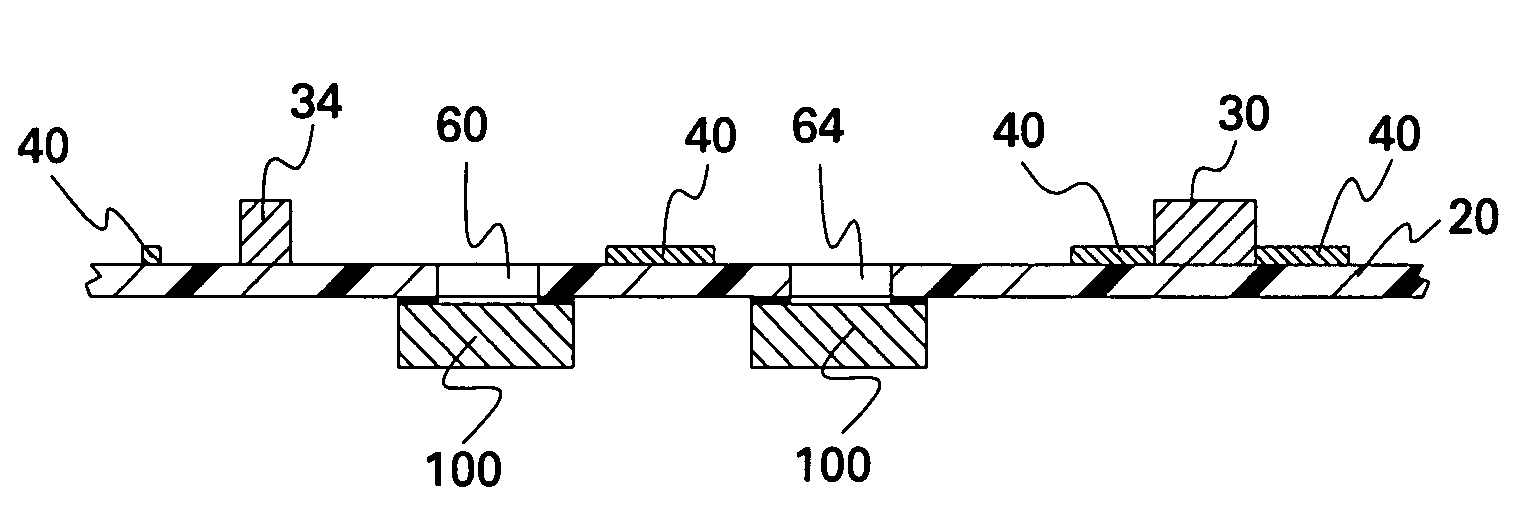
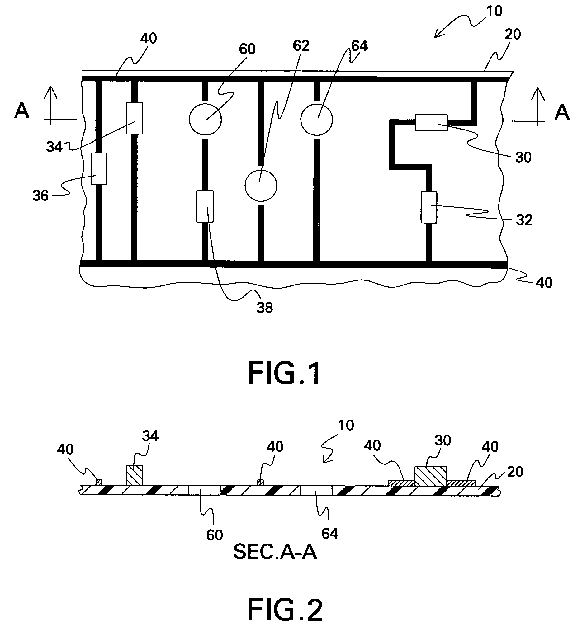
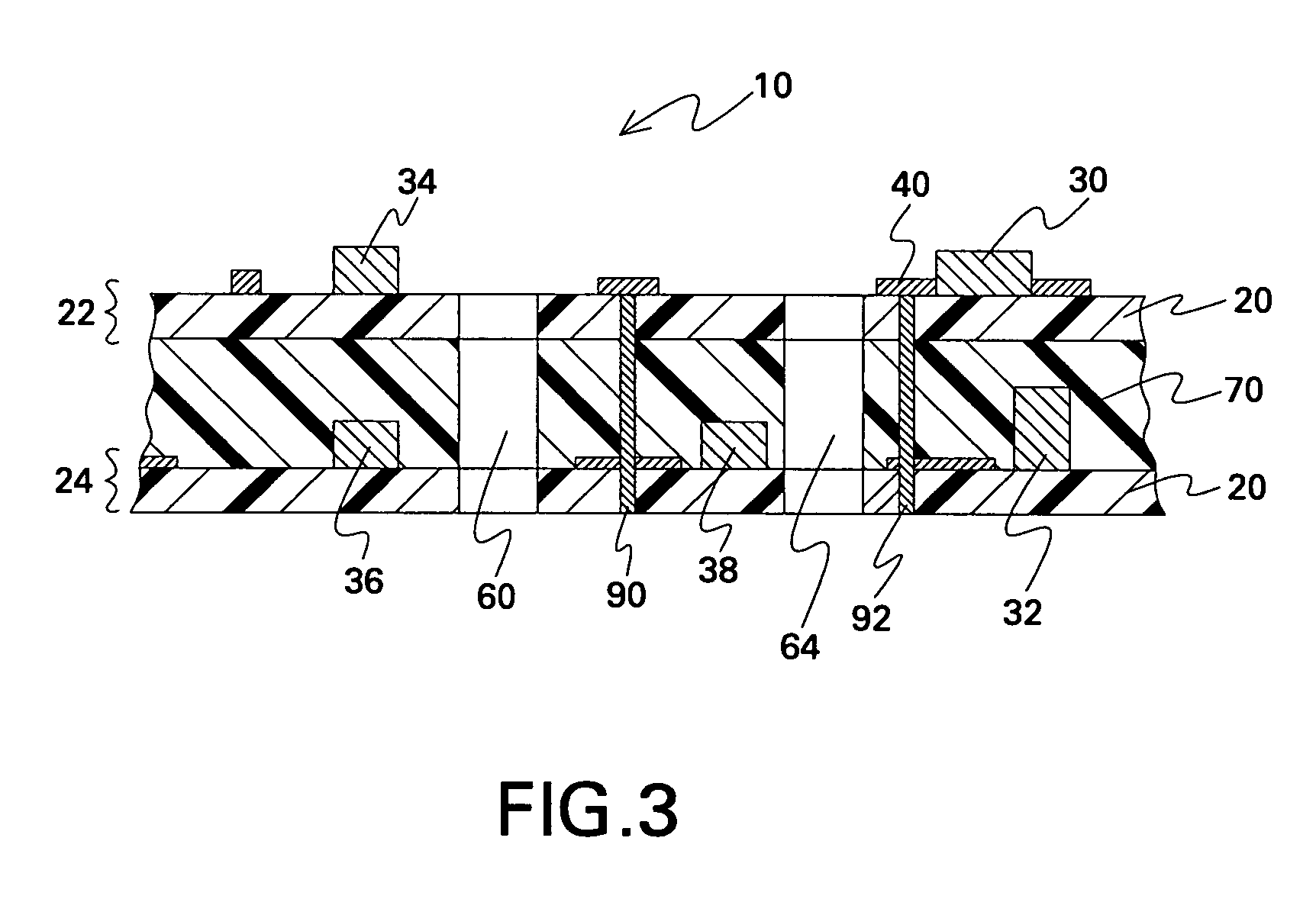
[0026]FIG. 1 shows schematically a section of a flexible interconnect structure 10 of the present invention. FIG. 2 is a cross-sectional view of flexib...


PUM


Abstract

A flexible interconnect structure allows for rapid dissipation of heat generated from an electrical device that includes light-emitting elements, such as light-emitting diodes (“LEDs”) and / or laser diodes. The flexible interconnect structure comprises: (1) at least one flexible dielectric film on which circuit traces and, optionally, electrical circuit components are formed and at least a portion of which is removed through its thickness; and (2) at least a heat sink attached to one surface of the flexible dielectric film opposite to the surface on which circuit traces are formed. The flexible interconnect structure can include a plurality of such flexible dielectric films, each supporting circuit traces and / or circuit components, and each being attached to another by an electrically insulating layer. Electrical devices or light sources having complex shapes are formed from such flexible interconnect structures and light-emitting elements attached to the heat sinks so to be in thermal contact therewith.

Description

BACKGROUND OF INVENTION[0001]The present invention relates to flexible interconnect structures that support circuits for controlling or operating electrical devices and light sources incorporating the same. In particular, the present invention relates to such flexible interconnect structures and devices that incorporate light-emitting elements and have improved thermal management capability.[0002]Light-emitting diodes (“LEDs”) are now widely applied in a variety of signs, message boards, and light sources. The relatively high efficacy of LEDs (in lumens per watt) is the primary reason for their popularity. Large power savings are possible when LED signals are used to replace traditional incandescent signals of similar luminous output. One aspect of LED technology that has not been satisfactorily resolved is the efficient management and removal of waste heat, especially for high optical power LEDs, requiring increased electrical power. The waste heat results in excessive junction tem...

Claims


Application Information

Patent Timeline
Patent Type & Authority Patents(United States)
IPC IPC(8): H05K1/16H01L25/075H01L33/62H05K1/02H05K1/18H05K3/46
CPCH05K1/0204H05K1/021H01L25/0753H01L33/62H05K1/185H05K1/189H05K3/4611H01L2924/0002H05K2201/10106H05K2201/10121H05K2201/10416H01L2924/00H05K2201/10219
Inventor BECKER, CHARLES ADRIANWEAVER, STANTON EARLSTECHER, THOMAS ELLIOT
Owner GENERAL ELECTRIC CO
Why Eureka
Try Eureka