Tunable micro electromechanical inductor

a micro electromechanical and inductor technology, applied in the direction of coupling devices, electrical apparatus, waveguides, etc., can solve the problems of less attention to design and less progress in the development of rf mems tunable inductors, and achieve the effect of fine resolution and compact siz

Active Publication Date: 2007-09-25
UNIV OF SOUTH FLORIDA
View PDF0 Cites 13 Cited by
  • Summary
  • Abstract
  • Description
  • Claims
  • Application Information

AI Technical Summary

Benefits of technology

[0009]A high inductance value is realized using a small length of high impedance line, which is provided by the narrow width inductive section of the center conductor. In a specific embodiment, this narrow width inductive section is of uniform width over the length of the small length section. In an additional embodiment, the center conductor is a meandered center conductor over the length of the narrow width section, thereby increasing the inductance ratio of the device.
[0010]In accordance with the present invention, the actuatable contact switch is in contact at one end with the center conductor and suspended above the coplanar waveguide bordering the narrow inductive section of the center conductor, such that upon actuation, the contact switch increases the effective width of the narrow inductive section, which in turn narrows the slot width between the center conductor and the ground conductor, resulting in a lower inductance value along the transmission line. Alternatively, the actuatable contact switch may be positioned on either or both of the ground conductors of the coplanar waveguide.
[0011]In a specific embodiment, the actuatable contact switch of the tunable inductor is a cantilever beam. The cantilever beam is positioned with one end in contact with the wider portion of the center conductor at one end of the narrow width section through a standoff post and then suspended over the length of the narrow width section with the other end of the cantilever positioned to make contact with the wider portion of the center conductor at the opposite end of the narrow section. Upon application of the DC bias to the DC bias line positioned below the cantilever beam, the cantilever beam is actuated, thereby bridging across the narrow section of the center conductor and increasing the effective width of the narrow section.

Problems solved by technology

However, to date much less progress has been made in developing RF MEMS tunable inductors.
Furthermore, less attention has been paid to designs that enable control in the sub-nH range as is potentially desirable for matching purposes in applications that use distributed loading of small capacitances, e.g. in loaded-line phase shifters.

Method used


Image

  • Tunable micro electromechanical inductor
  • Tunable micro electromechanical inductor
  • Tunable micro electromechanical inductor

Examples


Embodiment Construction

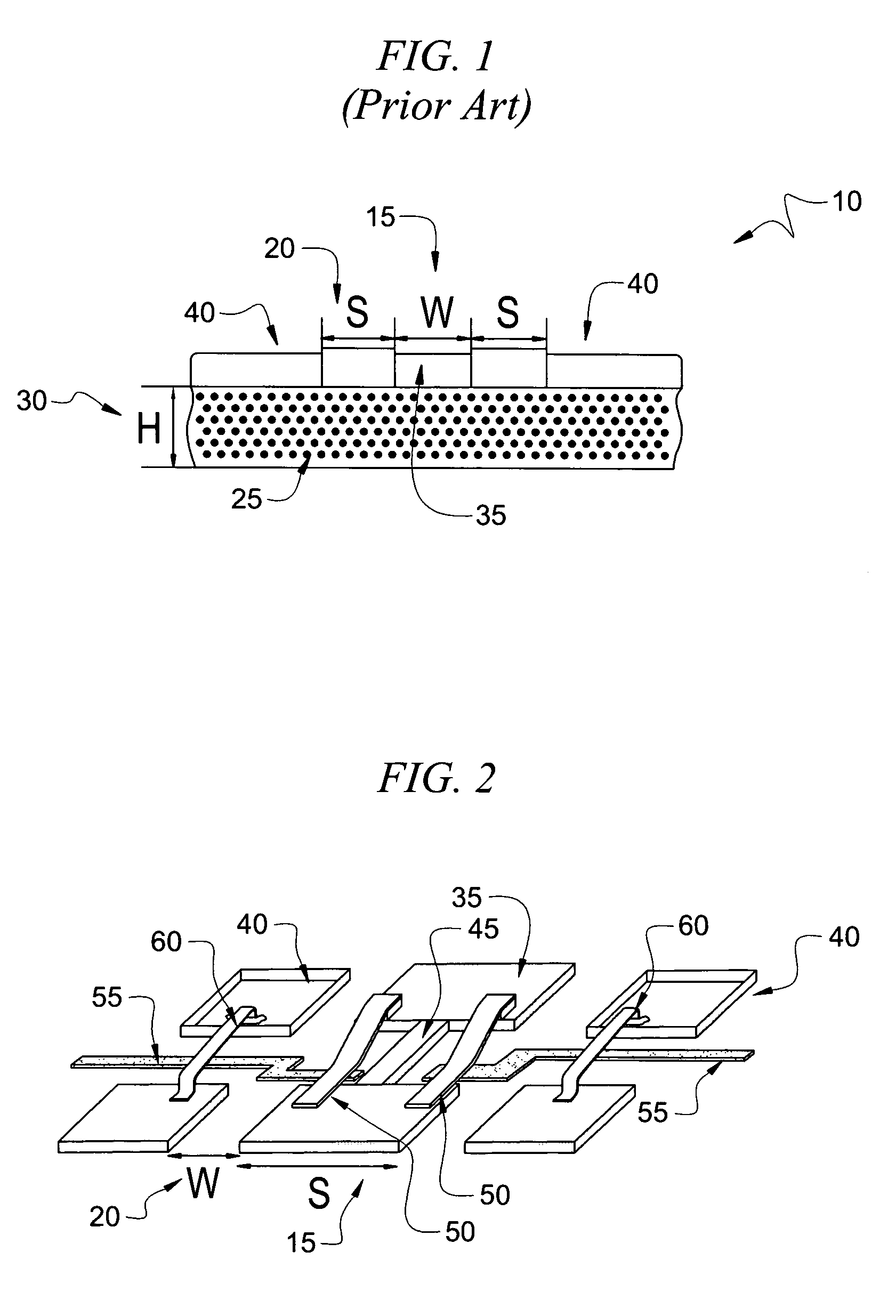
[0024]Coplanar waveguide (CPW) transmission lines are known in the art. With reference to FIG. 1, a CPW transmission line 10 consists of a center conductor 35 positioned between two ground conductors 40. The physical parameters that affect the impedance of a CPW transmission line 10 are the conductor width (W) 15, slot width (S) 20, dielectric constant of the substrate (∈T) 25, and the thickness (H) of the substrate 30. For a given dielectric constant 25 and the substrate thickness 30, a narrow width center conductor and a wide slot width result in high impedance. On the contrary, wide center conductor and a narrow slot width results in low impedance.

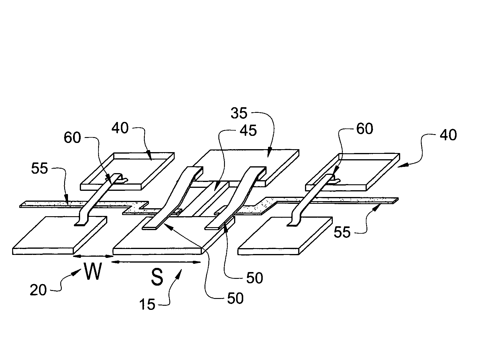
[0025]With reference to FIG. 2, in accordance with the present invention, a short length 35 of high impedance CPW transmission line is designed to emulate an inductor. In a particular embodiment, the short length 35 is approximately less than or equal to one quarter-wavelength λ / 4. As such, in accordance with the present invention a dig...


PUM


Abstract

The present invention provides a monolithic inductor developed using radio frequency micro electromechanical (RF MEMS) techniques. In a particular embodiment of the present invention, a tunable radio frequency microelectromechanical inductor includes a coplanar waveguide and at least one direct current actuatable contact switch positioned to vary the effective width of a narrow inductive section of the center conductor of the CPW line upon actuation the DC contact switch.

Description

CROSS REFERENCE TO RELATED APPLICATIONS[0001]This application claims priority to U.S. Provisional Patent Application No. 60 / 522,275, “A Tunable Micro Electromechanical Inductor”, filed Sep. 9, 2004.STATEMENT OF INTEREST[0002]This work has been supported by National Science Foundation grant 2106-301-LO and Raytheon Systems grant 2106-315-LO.BACKGROUND OF INVENTION[0003]The design of microwave and millimeter wave electronics requires components that provide a capability for impedance matching, and / or tuning. Impedance matching is the process through which signals are made to propagate through a high frequency network with a specific amount of reflection, typically as low as possible.[0004]Two of the most common types of components used for impedance matching are capacitors and inductors. Radio frequency micro electromechanical (RF MEMS) techniques have in the past been used to fabricate state-of-the-art tunable capacitors in a variety of different forms. However, to date much less pro...

Claims


Application Information

Patent Timeline
Patent Type & Authority Patents(United States)
IPC IPC(8): H01P1/10H01P3/08
CPCH01P1/127H01P5/04H01F21/04
Inventor WELLER, THOMASLAKSHMINARAYANAN, BALAJIBALACHANDRAN, SRINATH
Owner UNIV OF SOUTH FLORIDA
Why Eureka
Try Eureka