

Tunable Micro Electromechanical Inductor
- Summary
- Abstract
- Description
- Claims
- Application Information
AI Technical Summary
Benefits of technology
Problems solved by technology
Method used
Image

Examples
Embodiment Construction
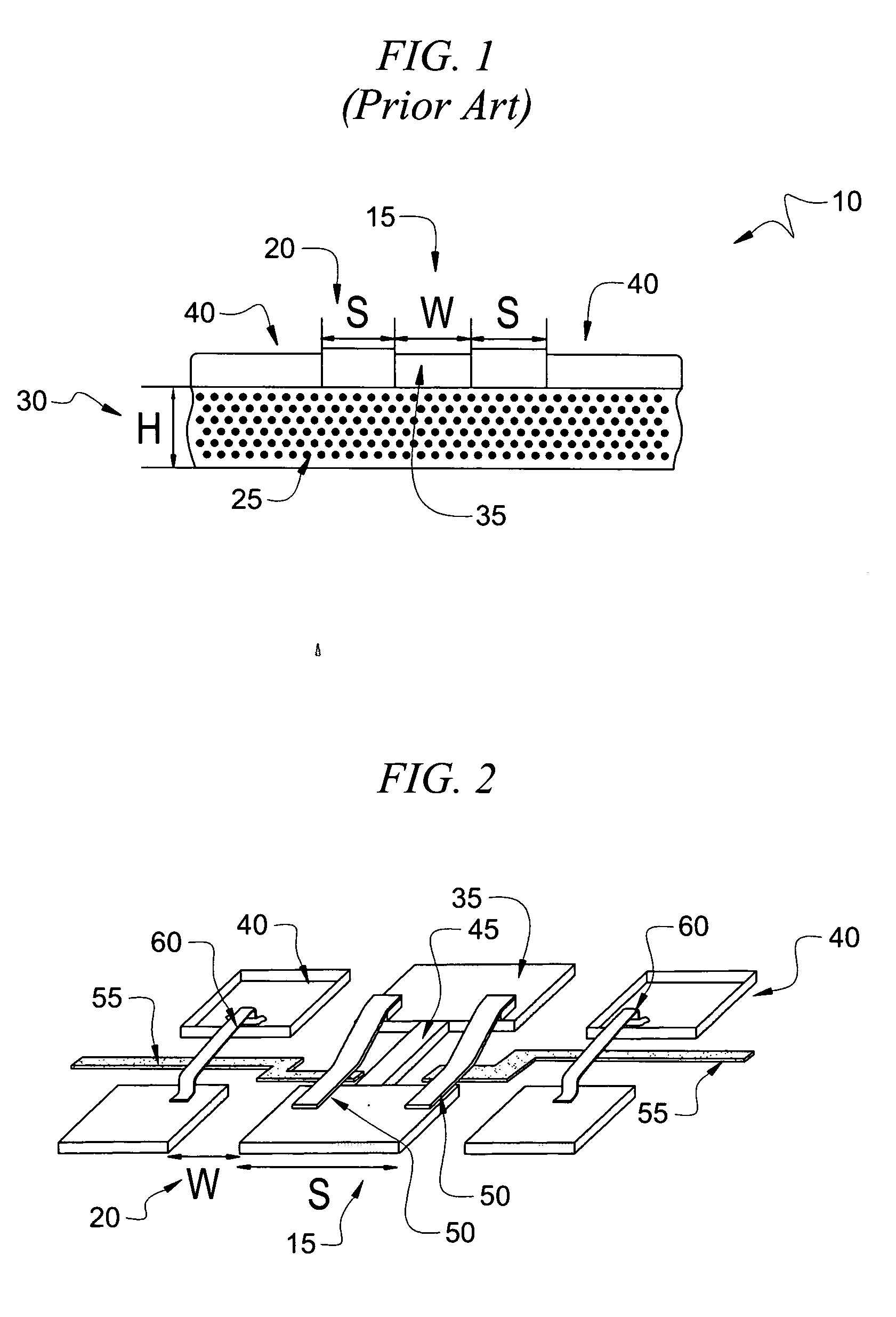
[0024] Coplanar waveguide (CPW) transmission lines are known in the art. With reference to FIG. 1, a CPW transmission line 10 consists of a center conductor 35 positioned between two ground conductors 40. The physical parameters that affect the impedance of a CPW transmission line 10 are the conductor width (W) 15, slot width (S) 20, dielectric constant of the substrate (εT) 25, and the thickness (H) of the substrate 30. For a given dielectric constant 25 and the substrate thickness 30, a narrow width center conductor and a wide slot width result in high impedance. On the contrary, wide center conductor and a narrow slot width results in low impedance.
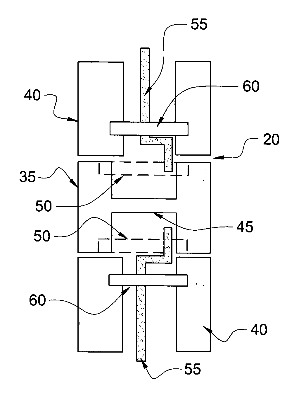
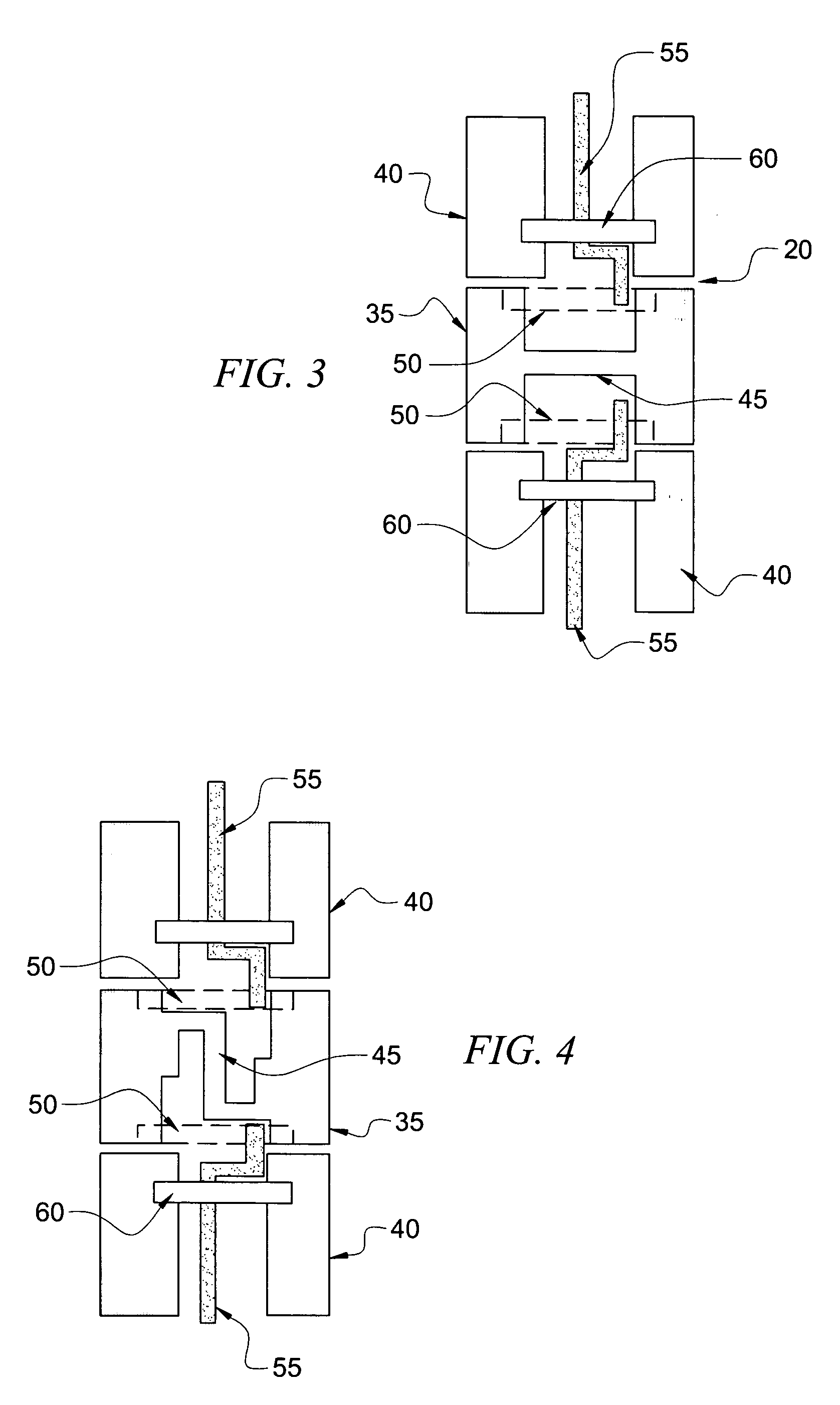
[0025] With reference to FIG. 2, in accordance with the present invention, a short length 35 of high impedance CPW transmission line is designed to emulate an inductor. In a particular embodiment, the short length 35 is approximately less than or equal to one quarter-wavelength λ / 4. As such, in accordance with the present invention a ...
PUM
 Abstract
Description
Claims
Application Information