Optical system for taking image

Active Publication Date: 2007-09-25
LARGAN PRECISION
View PDF1 Cites 77 Cited by
  • Summary
  • Abstract
  • Description
  • Claims
  • Application Information

AI Technical Summary

Benefits of technology

[0041]The optical system can maintain a good

Problems solved by technology

Therefore, the demand for the image quality becomes increasingly urgent.
However, the disadvantages of this conventional optical system are as follows: firstly, the arrangement of too many spherical lens elemen

Method used


Image

  • Optical system for taking image
  • Optical system for taking image
  • Optical system for taking image

Examples


first embodiment

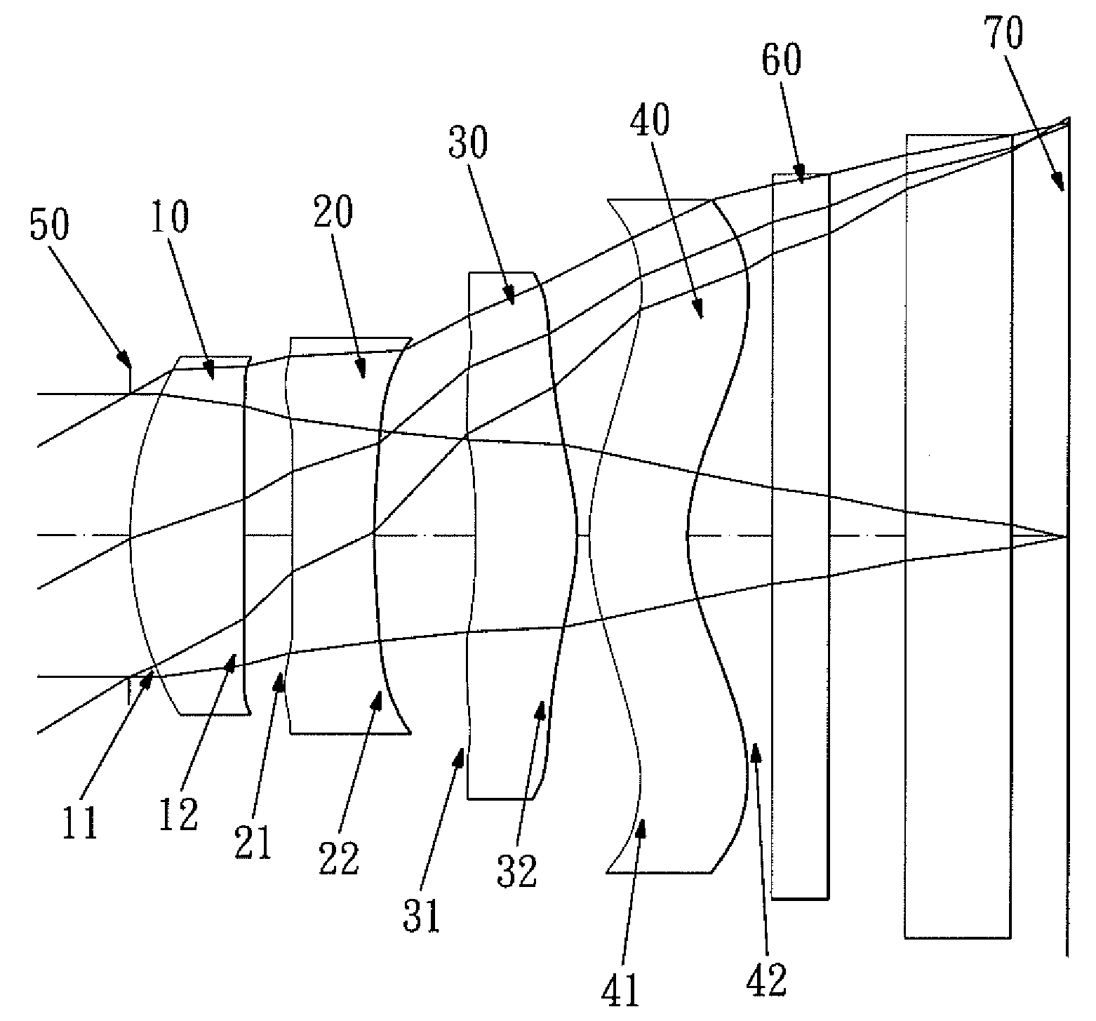
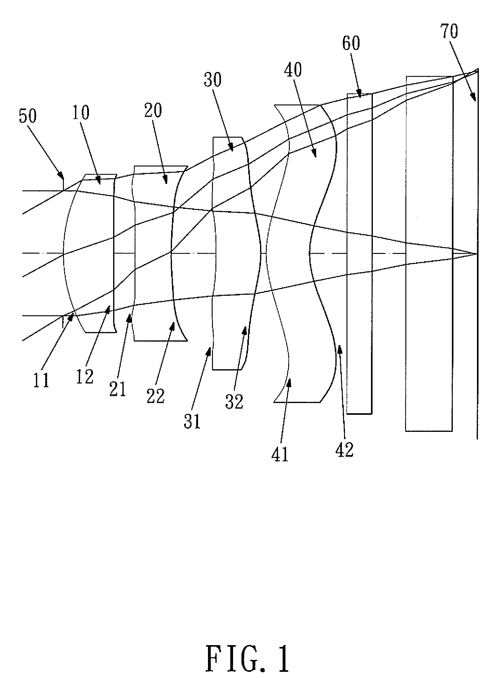
[0050]The optical system of the first embodiment comprises four lens elements with refractive power, from the object side to the image side:

[0051]A first lens element 10 with positive refractive power has a convex front surface 11 and a concave rear surface 12.

[0052]A second lens element 20 with negative refractive power has a concave front surface 21 and a concave rear surface 22.

[0053]A third lens element 30 with positive refractive power has a concave front surface 31 and a convex rear surface 32.

[0054]A fourth lens element 40 with positive refractive power has a convex front surface 41 and a concave rear surface 42.

[0055]An aperture stop 50 is located in front of the first lens element 10 for controlling the brightness of the optical system.

[0056]An IR cut filter 60 is located behind the fourth lens element 40 and has no influence on the focal length of the optical system.

[0057]And an image plane 70 is located behind the IR cut filter 60.

[0058]In the optical system, the Abbe num...

second embodiment

[0081]The Abbe number of the second lens element in the second embodiment is V2, and V2=23.4.

[0082]The first lens element 10, the second lens element 20, the third lens element 30, and the fourth lens element 40 are all made of plastic injection molding. The respective surfaces of the lenses are all aspheric, an inflection point is formed on the aspheric rear surface 42 of the fourth lens element 40, and the equation of the curve of the aspheric surfaces of the second embodiment is the same as that of the first embodiment.

[0083]In the second embodiment, the refractive index of the first lens element is N1, and N1=1.543, and the refractive index of the second lens element is N2, and N2=1.632, and the refractive index of the third lens element is N3, and N3=1.543.

[0084]In the second embodiment, the focal length of the first lens element with positive refractive power is f1, the focal length of the second lens element is f2, the focal length of the fourth lens element is f4, the focal ...

third embodiment

[0101]In the third embodiment, the refractive index of the first lens element is N1, and N1=1.543, and the refractive index of the second lens element is N2, and N2=1.632, and the refractive index of the third lens element is N3, and N3=1.543.

[0102]In the third embodiment, the focal length of the first lens element with positive refractive power is f1, the focal length of the second lens element is f2, the focal length of the fourth lens element is f4, the focal length of the optical system is f, they satisfy the relations: f / f1=1.41, |f / f2|=0.79, f / f4=−1.03.

[0103]In the third embodiment, the radius of curvature of the front surface of the first lens element is R1, and R1=1.28930 [mm], the radius of curvature of the front surface of the second lens element is R3, and it satisfies the relation: 1 / R3=0.15 [1 / mm].

[0104]In the third embodiment, the total length of the optical system is H, and H=4.56 [mm], the center thickness of the second lens element is CT2, and CT2=0.35 [mm], and the...


PUM


Abstract

An optical system comprises from the object side: a positive first lens element, a negative second lens element, a positive third lens element, a fourth lens element, and an aperture stop located between the object side of the optical system and the second lens element for controlling the brightness of the optical system. A radius of curvature R3 of a front surface of the second lens element satisfies the relation: −0.02 [1/mm]<1/R3<0.22 [1/mm], an Abbe number V2 of the second lens element is less than 40. A focal length of the fourth lens element is f4, a focal length of the optical system is f, they satisfy the relation: f/f4<0.1, at least one inflection point is formed on the rear surface of the fourth lens element.

Description

BACKGROUND OF THE INVENTION[0001]1. Field of the Invention[0002]The present invention relates to an optical system, and more particularly to a miniaturized optical system for taking image for a camera mobile phone.[0003]2. Description of the Prior Art[0004]In recent years, with the popularity of camera mobile phone, the image pickup lens assembly has been becoming thinner and thinner, and the photosensitive assembly of a general digital camera is nothing more than CCD (charge coupled device) or CMOS (Complementary Metal Oxide Semiconductor). Due to the advancement of semiconductor technique, the pixel size of photosensitive assembly has been being reduced continuously, and the development of the miniaturized image pickup lens assembly is toward the high resolution field. Therefore, the demand for the image quality becomes increasingly urgent.[0005]A conventional high resolution mobile phone's optical system usually consists of four lenses and comprises a front aperture stop, wherein...

Claims


Application Information

Patent Timeline
IPC IPC(8): G02B9/34
CPCG02B9/34G02B13/004
Inventor TANG, HSIANG CHICHEN, CHUN SHAN
Owner LARGAN PRECISION
Why Eureka
Try Eureka