Image forming device

a technology of forming device and rotary frame, which is applied in the direction of mechanical control device, electrographic process apparatus, instruments, etc., can solve the problems of increasing difficulty in reducing the size of the developing unit, and increasing the cost per sheet, so as to reduce the displacement of the rotary frame during the toner supply operation and reduce the burden on the environment. , the effect of simple structur

Inactive Publication Date: 2007-09-25
KYOCERA DOCUMENT SOLUTIONS INC
View PDF5 Cites 6 Cited by
  • Summary
  • Abstract
  • Description
  • Claims
  • Application Information

AI Technical Summary

Benefits of technology

[0013]Conventionally, when the toner supply member is inserted into or pulled out of the developing unit, it is necessary to operate a lock mechanism for locking the rotary frame of the developing device both clockwise and counterclockwise. In the device according to the present invention, the rotary frame is adapted to receive torque in the first direction when the toner supply member is inserted into the developing unit, and the lock mechanism is adapted to be capable of prohibiting the rotation of the rotary frame in the first direction, which is the direction of rotation of the rotary frame during the image forming operation. Consequently, in the lock mechanism in the device, the position of the rotary frame is maintained only by prohibiting the rotation of the rotary frame in the first direction. Namely, it is unnecessary to prepare a conventional two-way lock mechanism so that displacement of the rotary frame during the toner supplying operation is restrained with a simple structure.
[0020]In the device, the shutter is provided at the toner supply opening of the developing unit, and the shutter is opened so as to supply the toner into the developing device. The shutter is closed so as to stop the toner supply. Consequently, the toner does not leak from the toner supply opening of the developing unit into the device.
[0021]In the device according to the present invention, the rotary frame is adapted to receive torque in the first direction when the toner supply member is advanced into the developing unit, and the lock mechanism is adapted to be capable of prohibiting the rotation of the rotary frame in the first direction. Consequently, it is only necessary for the lock mechanism to prohibit the rotation of the rotary frame in the first direction. Namely, it is unnecessary to prepare a conventional two-way lock mechanism, so that displacement of the rotary frame during the toner supplying operation is restrained with a simple structure.

Problems solved by technology

As a result, it is difficult to reduce the developing unit in size.
Although it is possible to set a toner printing capability to 4,000 sheets or less in order to reduce the size of the developing unit, in that case the cost per one sheet increases.
In addition, when the toner is completely consumed, it is necessary to replace the developing units each time.
As a result, it increases the burden on the environment.
As a result, the lock mechanism generally has a difficult structure.

Method used


Image

  • Image forming device
  • Image forming device
  • Image forming device

Examples


Embodiment Construction

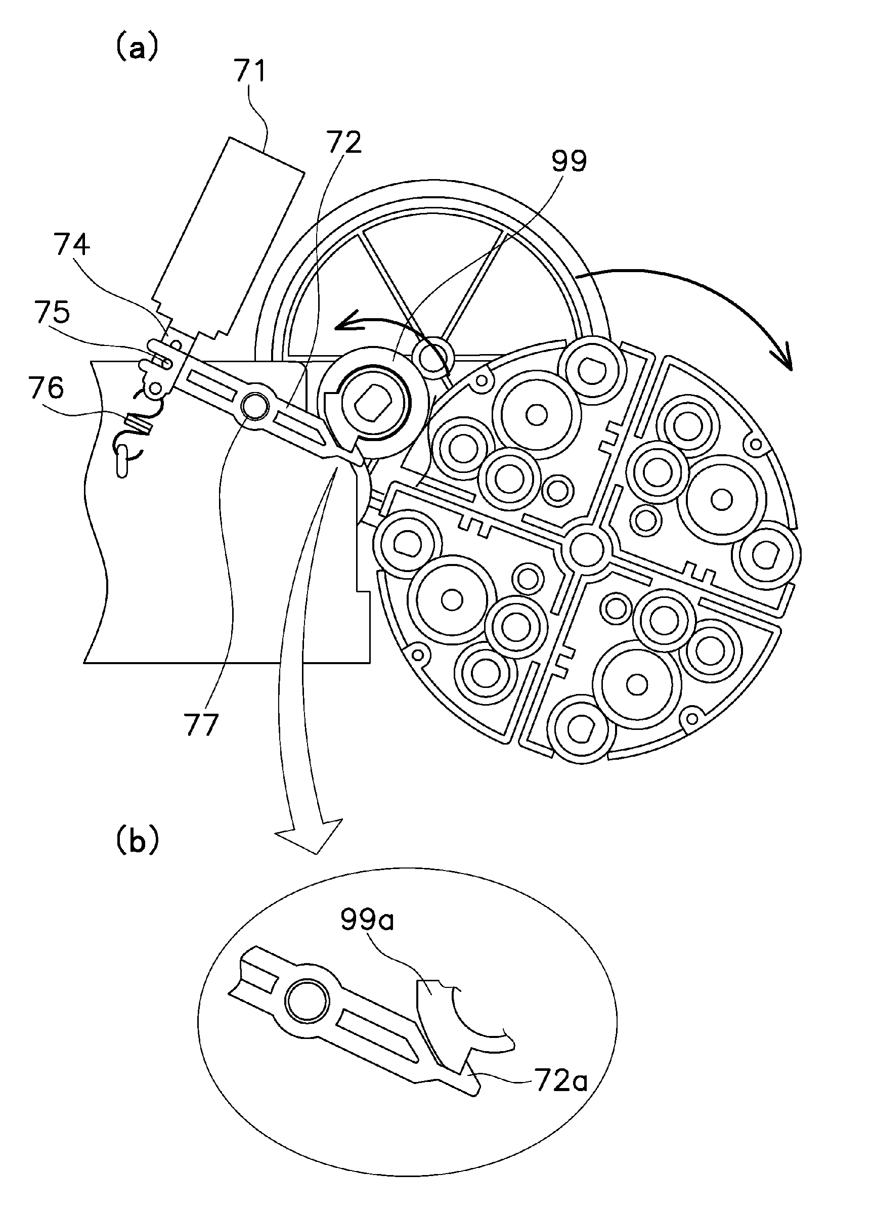
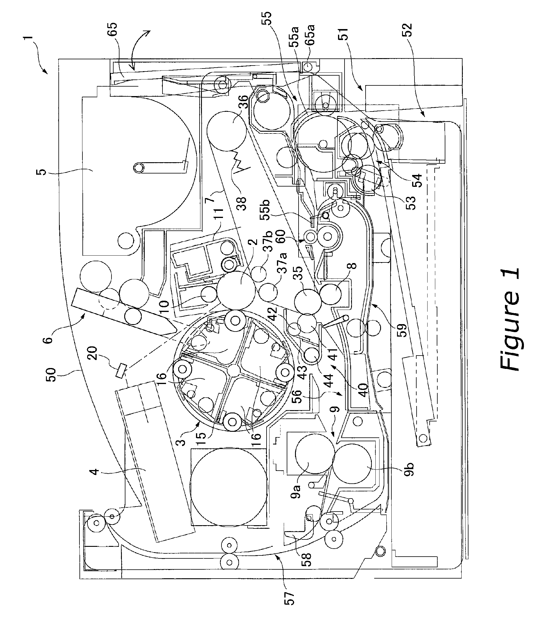
[0033]FIG. 1 shows a color printer 1 as a color image forming device according to one embodiment of the present invention. FIG. 1 is a view showing a frame format of the locations of each component, and thus details of each portion are omitted.

Overall Structure

[0034]The color printer 1 is connected to a computer, for example, and is capable of printing a color image on a sheet in accordance with image data sent from the computer. In this color printer 1, the right side of FIG. 1 is the side from which an operator operates the color printer 1. In the below description, the right side in FIG. 1 is referred to as the “front side” and the left side in FIG. 1 is referred to as the “rear side”.

[0035]The color printer 1 includes a photosensitive drum 2, a rotary developing device 3, a laser unit 4, a toner container 5, a toner supply device 6, an intermediate transfer belt 7, a secondary transfer roller 8, and a fixing device 9.

Photosensitive Drum

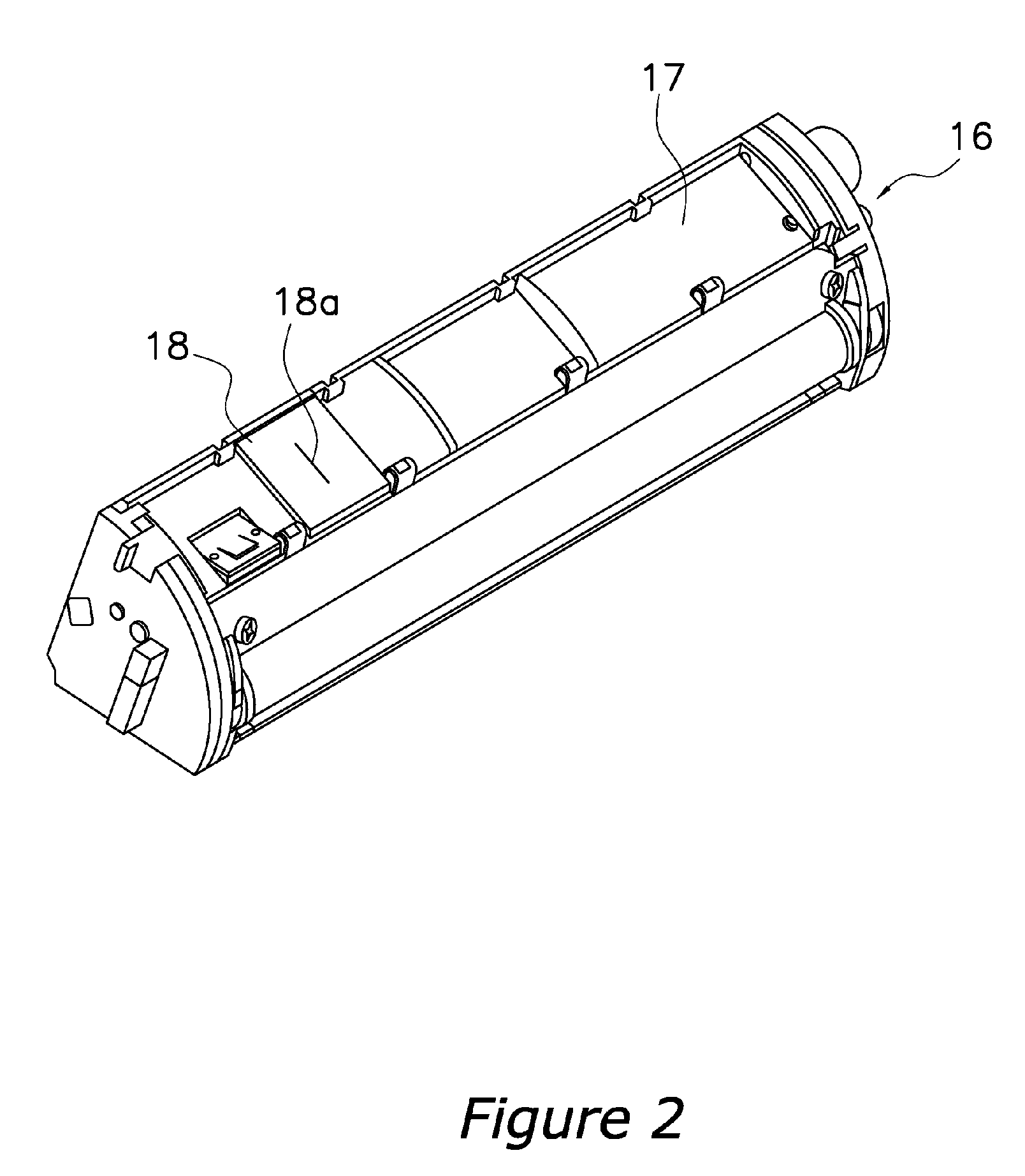
[0036]The photosensitive drum 2 has a surfa...


PUM


Abstract

An image forming device is disclosed which is provided with a simple lock mechanism for locking the position of the developing units on a rotary frame during toner supply. In the lock mechanism, a solenoid is turned off and a rod is moved downward by a spring so that a second member is rotated counterclockwise and a claw at the end thereof is engaged with a protruding portion of a first member. In this state, a rotary frame driving gear is prohibited from rotating, i.e., the rotary frame is locked. Thus, it is unnecessary to prepare a conventional two-way lock mechanism, and displacement of the rotary frame during toner supply is restrained with a simple structure.

Description

BACKGROUND OF THE INVENTION[0001]1. Field of the Invention[0002]The present invention relates to an image forming device, and more particularly to an image forming device including a rotary developing device having a plurality of developing units and a rotary frame that maintains the developing units in a circumferential direction in order to place each of the developing units opposite the image bearing member by means of rotation.[0003]2. Background Information[0004]An image forming device utilizing an electrophotographic system includes a photosensitive drum as an image bearing member and other devices located circumferentially around the drum, such as a charger, an exposure device, a developing device, a transfer device, a cleaning device, and so on. In addition, a fixing device is provided downstream of the photosensitive drum in a direction in which the transfer media are conveyed. In this image forming device, first, a surface of the photosensitive drum is uniformly charged by...

Claims


Application Information

Patent Timeline
Patent Type & Authority Patents(United States)
IPC IPC(8): G03G15/01G05G15/08
CPCG03G15/0121G03G15/0877G03G15/0879G03G15/0886G03G2215/0177G03G2215/0685
Inventor TOMOE, TETSURO
Owner KYOCERA DOCUMENT SOLUTIONS INC
Why Eureka
Try Eureka