HVAC/R monitoring apparatus and method

a technology of hvac/r and monitoring apparatus, which is applied in the field of hvac/r monitoring apparatus and methods, can solve the problems of increasing the cost of operating the hvac/r system, inconvenience for persons living in or using the facility, damage to property or spoilage of perishable goods, etc., and achieves the effect of facilitating maintenance of the hvac/r system

Inactive Publication Date: 2007-09-25
HEFEI JIANQIAO SCI TECH DEV +1
View PDF23 Cites 185 Cited by
  • Summary
  • Abstract
  • Description
  • Claims
  • Application Information

AI Technical Summary

Benefits of technology

[0014]Advantageously, the apparatus of the present invention facilitates maintaining an HVAC / R system in optimum operating condition by alerting users and service technician to potential problems with the system. Accordingly, service technician having access to the information provided by the monitoring apparatus can determine the corrective action necessary to restore the HVAC / R system to proper working order, without having to first physically inspect the system. This ensures that the service technician will be better able to restore the system to proper working order in an efficient manner.

Problems solved by technology

Moreover, as the operating efficiency and capacity of the HVAC / R system decrease, the cost of operating the HVAC / R system increases.
When HVAC / R systems are not operating efficiently, or when they fail, the result is often discomfort to the persons residing in or utilizing the facilities, or even damage to property or the spoilage of perishable goods, such as food stored in a refrigerated system.
Unfortunately, homeowners and other users are often unaware of the operating efficiency of their HVAC / R systems or the warning signs of an impending failure, and are generally unable to repair the HVAC / R system themselves.
When a fault is detected, the computer will illuminate the flash code lamp, and some systems may also store the diagnostic trouble code in its memory.
Moreover, since it is impractical for service technician to have on hand all of the various components that might be necessary to restore the HVAC / R system to proper working order, the service technician must usually travel to another location to retrieve the necessary parts and subsequently return to the work location to repair the HVAC / R system.
In the worst case, a part may not be readily available and must be ordered, whereby the service technician must return at a later date, further delaying repair and inconveniencing the owner or user of the system.
This is particularly troublesome for HVAC / R systems which are located in remote areas.

Method used


Image

  • HVAC/R monitoring apparatus and method
  • HVAC/R monitoring apparatus and method
  • HVAC/R monitoring apparatus and method

Examples


Embodiment Construction

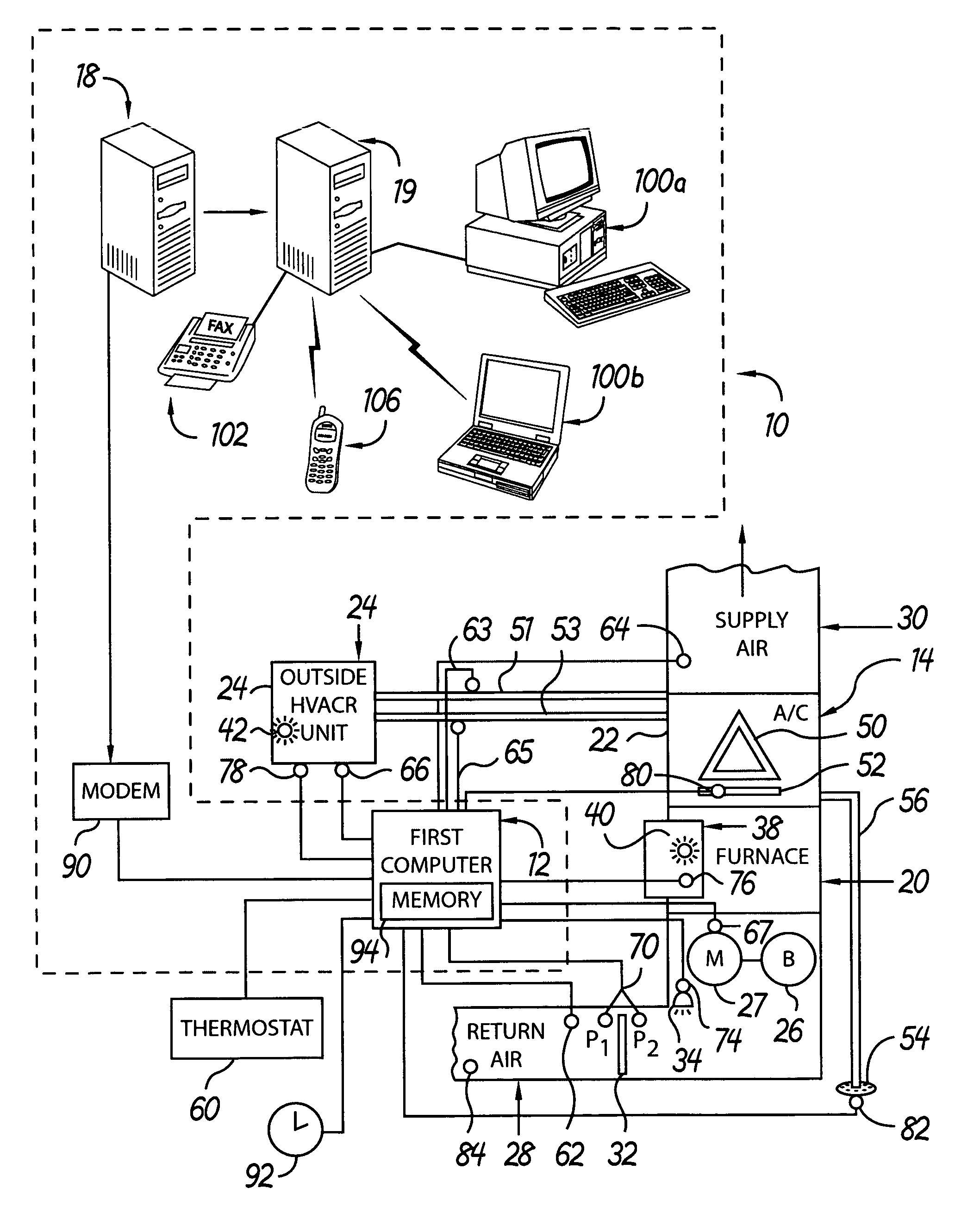
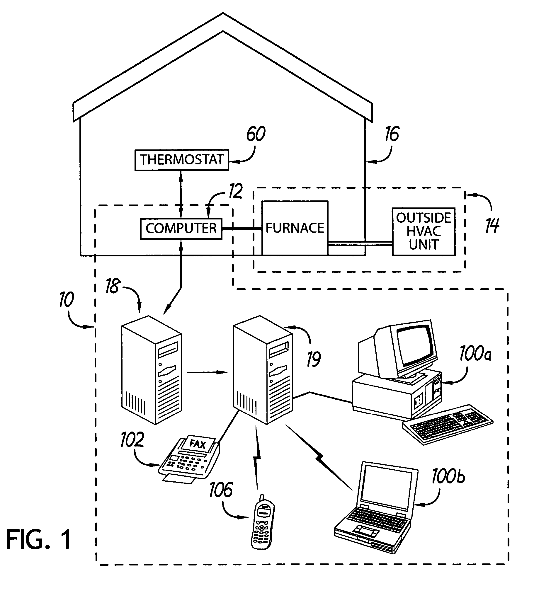
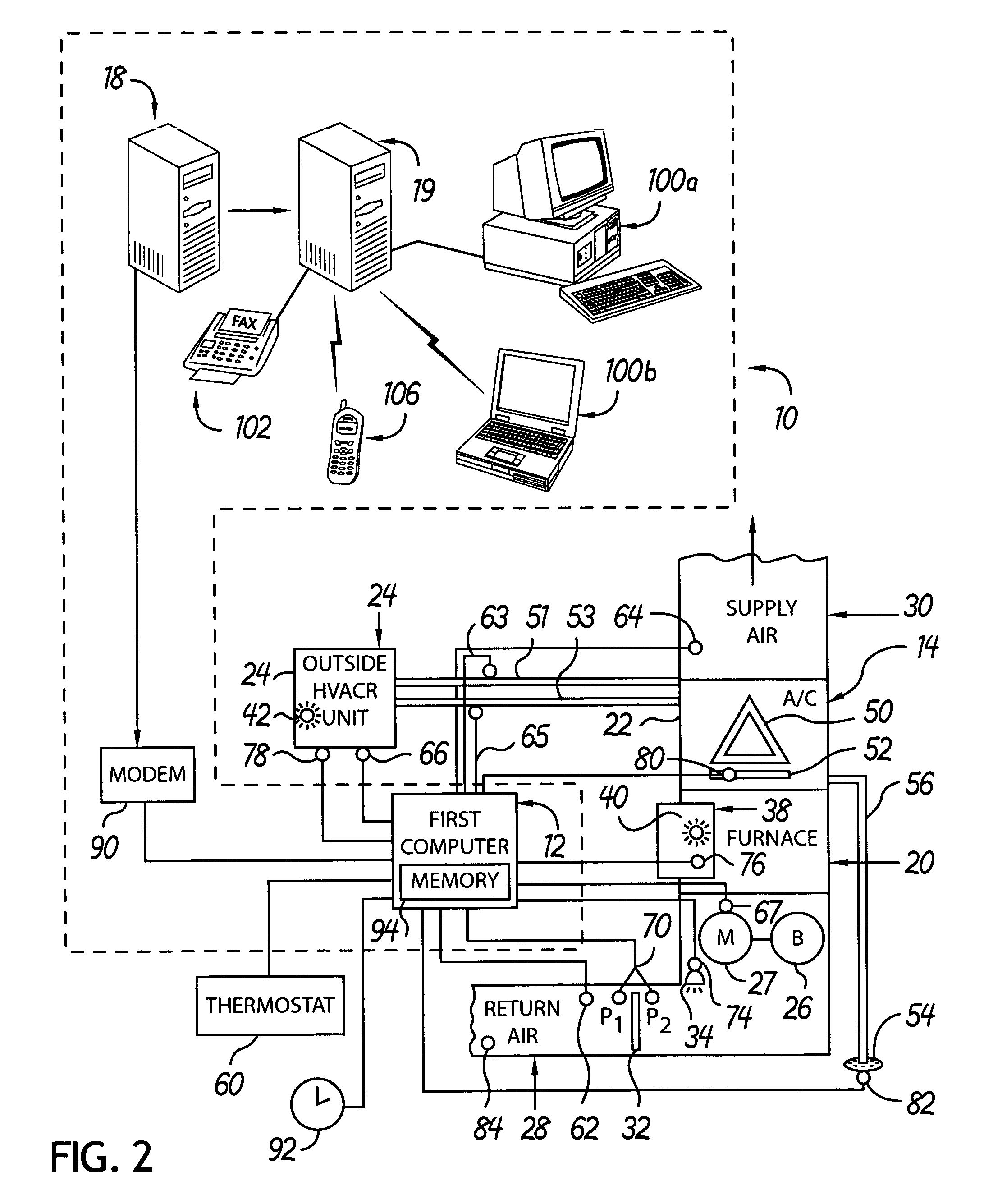
[0023]Referring to FIG. 1, there is shown an exemplary monitoring apparatus 10 according to the principles of the present invention. The monitoring apparatus 10 includes a first computer 12 located proximate an HVAC / R system 14 of a building 16. The first computer 12 may be located on the structure of a component of the HVAC / R system 14, or it may be positioned at a location in the building 16 which is more readily accessible to service technician. The monitoring apparatus 10 further includes an array of sensors operatively coupled to various components of the HVAC / R system 14 for sensing various operating data of the HVAC / R system 14 and communicating this data to the first computer 12, as will be described more fully below. The monitoring apparatus 10 further includes a second computer 18, typically at a location remote from the first computer 12 and configured to receive communications from the first computer 12 related to the operating data of the HVAC / R system 14. The second co...


PUM


Abstract

An apparatus and method for monitoring the operation of a heating, ventilation, air conditioning and / or refrigeration (HVAC / R) system includes a first computer located on or near the HVAC / R system and a plurality of sensors positioned to sense various operating parameters of the HVAC / R system. The sensors communicate the sensed parameters to the first computer. When the first computer detects a condition of the HVAC / R system that requires attention, based on parameters sensed by the sensors, the first computer communicates with a second computer located remote from the first computer and transmits a message related to the condition.

Description

CROSS-REFERENCE TO RELATED APPLICATIONS[0001]This application claims the benefit of co-pending U.S. Provisional Application No. 60 / 527,903, filed Dec. 8, 2003.FIELD OF THE INVENTION[0002]The present invention relates generally to heating, ventilation, air conditioning and / or refrigeration (HVAC / R) systems, and more particularly to an apparatus and method for monitoring HVAC / R systems.BACKGROUND OF THE INVENTION[0003]Heating, ventilation, air conditioning and / or refrigeration systems are widely used to regulate the temperature of buildings and other facilities, such as residential homes, office buildings, storage facilities, and other structures where it is desired to heat or cool the facility. In such applications, it is important to ensure that the mechanical systems for heating or cooling the facility are properly maintained. Specifically, it is known that the operating efficiency of a HVAC / R system decreases dramatically with even a minimal lack of maintenance to the system. As t...

Claims


Application Information

Patent Timeline
Patent Type & Authority Patents(United States)
IPC IPC(8): G05D23/00G05B23/02
CPCF24F11/0086G05B15/02G05B23/0235G05B2219/13G05B2219/2642F24F11/30G05B2223/06F24F11/38
Inventor NICHOLS, JARED G.CORBMAN, PAUL T.
Owner HEFEI JIANQIAO SCI TECH DEV
Why Eureka
Try Eureka