Unlocking jig

a technology of locking jigs and jigs, which is applied in the direction of coupling device connections, manufacturing tools, and securing/insulating coupling contact members, etc., can solve the problems of inconvenient conventional methods, and achieve the effect of smooth operation of the operation par

Active Publication Date: 2007-10-02
SUMITOMO WIRING SYST LTD
View PDF12 Cites 14 Cited by
  • Summary
  • Abstract
  • Description
  • Claims
  • Application Information

AI Technical Summary

Benefits of technology

[0011]The unlocking jig allows the flexing pieces to be unlocked simultaneously from the corresponding locks. Therefore, the removing operation is performed easily and efficiently, unlike the conventional art.
[0013]The guide and the to-be-guided portion engage while operating the operation part to remove the member from the housing. Therefore it is possible to operate the operation part smoothly.

Problems solved by technology

Therefore the conventional method is inconvenient.

Method used


Image

  • Unlocking jig
  • Unlocking jig
  • Unlocking jig

Examples


Embodiment Construction

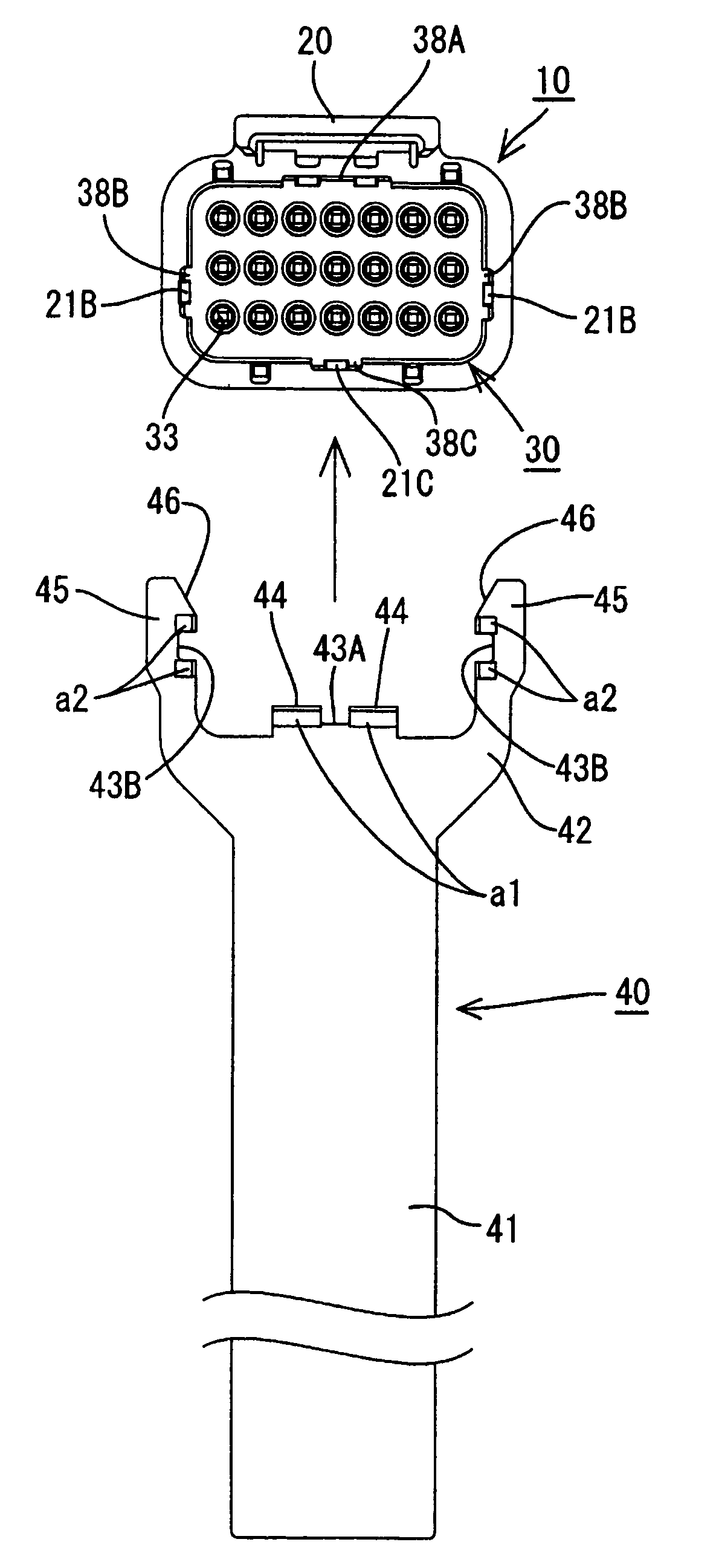
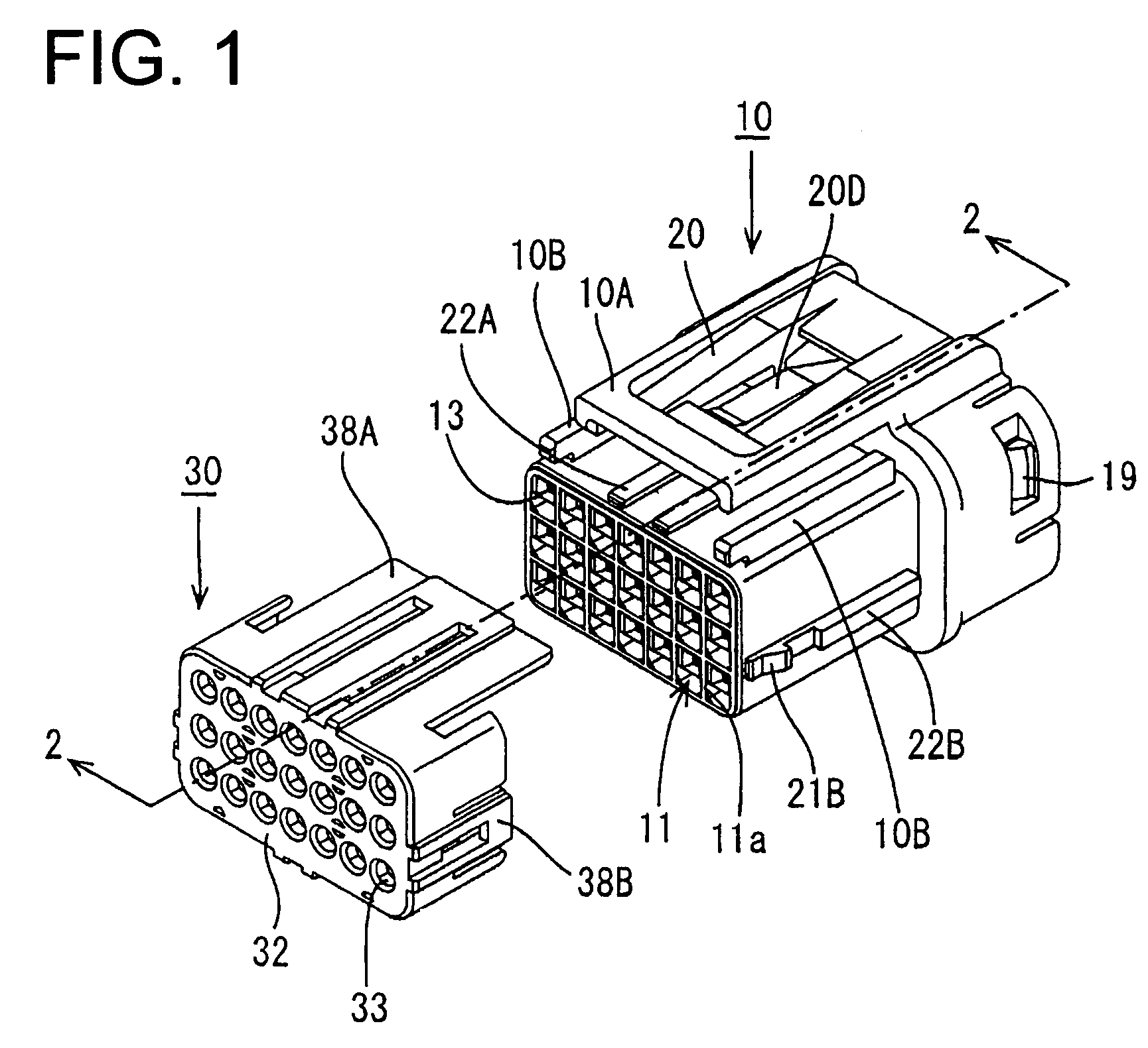
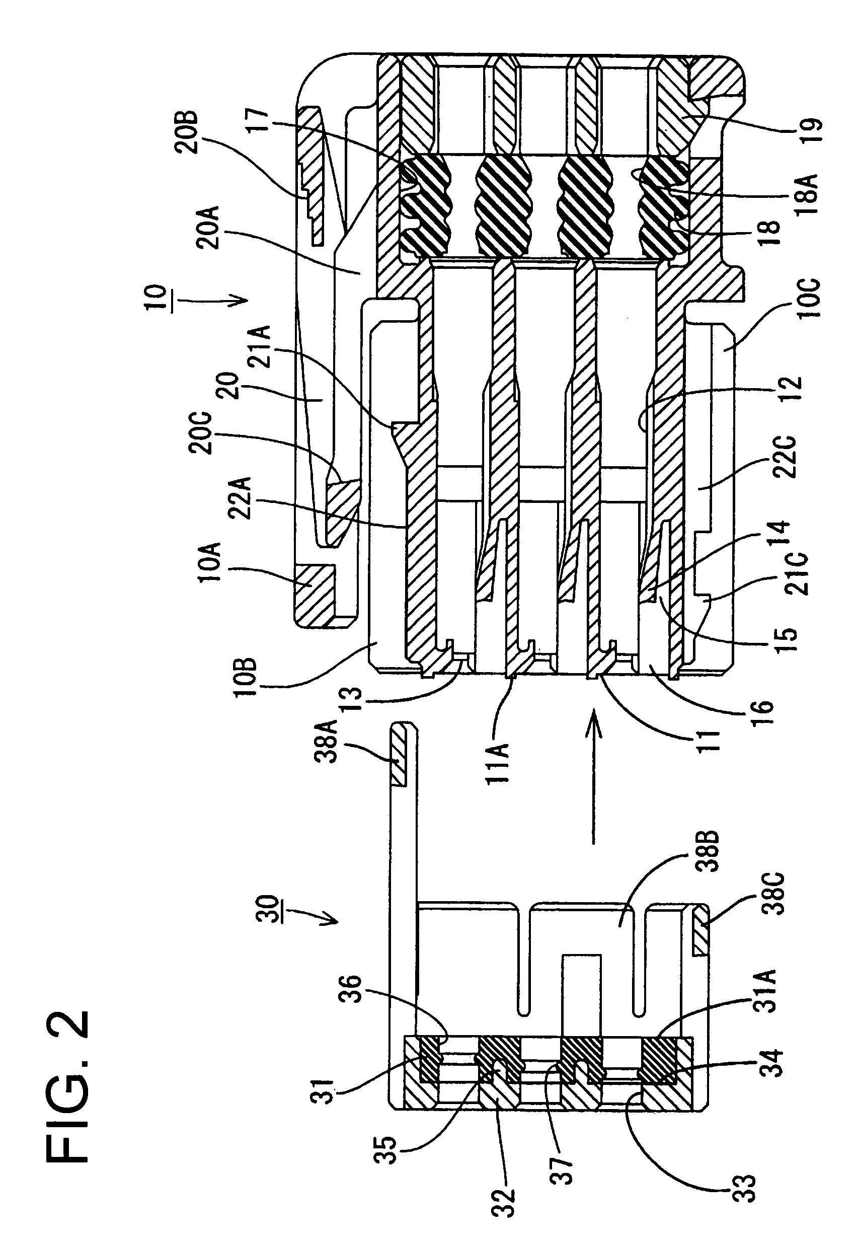
[0024]A waterproof connector includes a female housing identified by the numeral 10 in FIGS. 1 and 2. The female housing 10 is made of a synthetic resin and has a front end 11 and an opposite rear end. Portions of the female housing 10 adjacent the front end 11 are substantially block-shaped so that the female housing 10 can be fit in a hood of a male housing (not shown).

[0025]Cavities 12 extend through the female housing 10 in a front-to-back direction, as shown in FIGS. 1 and 2. The cavities 12 are arranged in seven rows and three stages that correspond to positions of male terminal fittings of the male housing. A terminal fitting insertion opening 13 extends into the front of each cavity 12 for receiving the male terminal fitting, and a lance 14 is formed on a bottom wall of each cavity 12. The lance 14 is elastically deformable toward a flexing space 15 disposed at a lower portion of the cavity 12. An insertion opening 16 extends into the front of the flexing space 15 and receiv...


PUM

PropertyMeasurementUnit
timeaaaaaaaaaa
flexing rigidityaaaaaaaaaa
flexibleaaaaaaaaaa

Abstract

An unlocking jig (40) is fit on a female housing (10) from below. As a result, a guide groove (43A) on a bottom portion (43) of the unlocking jig (40) engages a convexity (22C) on a lower surface of the female housing (10) and a guide groove (43B) on an arm (45) engages a convexity (22B) on a side surface of the female housing (10). The unlocking jig (40) has unlocking claws (a1, a2) that engage short locking pieces (38B, 38C) when the unlocking jig (40) is moved and unlock the short locking pieces (38B, 38C) from locks (22B, 22C) on the housing (10).

Description

BACKGROUND OF THE INVENTION[0001]1. Field of the Invention[0002]The invention relates to an unlocking jig for unlocking a plurality of flexing pieces from locking projections that prevent separation between a housing and a member mounted on the housing.[0003]2. Description of the Related Art[0004]U.S. Pat. No. 6,250,962 and FIG. 10 herein disclose a waterproof connector. With reference to FIG. 10, the waterproof connector includes a female housing 1 with opposite front and rear ends, and receives female terminal fittings 2 that are mounted to ends of electric wires 3. A waterproof rubber seal 4 is mounted on the rear side of a female housing 1 for waterproofing the electric wires 3 and is held in place by a hold-down member 5 that is installed on the female housing 1. More particularly, locking projections 6a and 6b are formed on the side surfaces at the rear of the female housing 1 and flexing pieces 7a and 7b project from the hold-down member 5 at locations aligned with the lockin...

Claims


Application Information

Patent Timeline
Patent Type & Authority Patents(United States)
IPC IPC(8): B23P19/00H01R13/436B25B27/14H01R13/633H01R43/22
CPCH01R13/4367H01R43/22H01R13/633Y10T29/53209Y10T29/53239Y10T29/53222Y10T29/53213
Inventor ICHIDA, KIYOFUMITANAKA, NOBUYOSHI
Owner SUMITOMO WIRING SYST LTD
Why Eureka
Try Eureka