Control apparatus for an internal combustion engine
What is AI technical title?
AI technical title is built by Patsnap AI team. It summarizes the technical point description of the patent document.
a control apparatus and internal combustion engine technology, applied in the direction of electrical control, process and machine control, instruments, etc., can solve the problems of deteriorating the driveability of the vehicle, pressure difference p has not yet reached the lower limit value of normal pressure difference, and the abnormal flow rate of egr of exhaust gas cannot be easily found or recognized by the driver, so as to achieve high reliability the effect of failure determination
Inactive Publication Date: 2007-10-02
MITSUBISHI ELECTRIC CORP
View PDF7 Cites 26 Cited by
Summary
Abstract
Description
Claims
Application Information
AI Technical Summary
This helps you quickly interpret patents by identifying the three key elements:
Problems solved by technology
Method used
Benefits of technology
Benefits of technology
[0086]The present invention is intended to solve the problems as referred to above, and has for its object to obtain a control apparatus for an internal combustion engine which is capable of preventing the mis-detection of failure thereby to achieve a highly reliable failure determination for an EGR system by properly compensating for an error in the intake pipe pressure due to the influences of a change in the number of revolutions per minute of the engine caused by the difference of a deceleration state, and of a change in the amount of bypass air.
[0087]Another object of the present invention is to obtain a control apparatus for an internal combustion engine which is capable of increasing a temperature region in which failure detection is executed, and preventing mis-detection thereby to achieve a highly reliable failure determination for an EGR system by always performing a failure determination at constant intake pipe pressure thereby to compensate for an error in the intake pipe pressure (including the influences of the tolerances of component parts and deposits) caused by a change in the number of revolutions per minute of the engine or by a change in the amount of bypass air including during an engine cooling state.
[0090]According to the present invention, when the deceleration state of the engine (including during a fuel cut-off operation) is detected, the EGR valve is forced to open and close after the intake pipe pressure has been adjusted to be within the predetermined range by using the intake pipe pressure adjustment section, so that a pressure change index value obtained based on the intake pipe pressure at the time of the forced opening and closing of the EGR valve is compared with a failure determination value so as to make a determination as to whether the EGR control section is in failure. As a result, a failure determination can always be done with the intake pipe pressure becoming a predetermined characteristic with respect to the number of revolutions per minute of the engine, whereby it is possible to precisely compensate for an error in the intake pipe pressure Pb due to a change in the amount of bypass air caused by the engine load, the difference of the engine cooling state, etc., including the tolerances of component parts and the influence of deposits, thereby making it possible to perform an accurate failure determination for the EGR control device.
Problems solved by technology
If such a state is left, there will arise a problem that a large amount of NOx continues to be generated, but such an abnormal flow rate of EGR of the exhaust gas can not be easily found or recognized by the driver.
However, when the EGR valve 12 is opened and / or closed during the steady-state operation of the engine 1, the torque generated by the engine 1 is varied, thereby deteriorating the driveability of the vehicle.
On the other hand, when ΔP
Accordingly, when a determination is made as to whether the EGR control device is in failure, by detecting the pressure difference ΔP according to the change in the amount of intake air Qa due to the presence and absence of EGR in the deceleration state, it might become, in the worst case, unable to detect the failure state of the EGR control device, or the normal state thereof might be mistakenly detected as a failure state thereof.
As a result, in a device that makes a failure determination based on the amount of change of the intake pipe pressure Pb (the pressure difference ΔP) according to the change in the amount of intake air Qa due to the presence and absence of EGR, there is a possibility, in the worst case, of becoming unable to detect a failure state or of mis-detecting a normal state as a failure state.
Moreover, as a consequence of this, there is also another problem that in case where a failure determination is made based on the amount of change of the intake pipe pressure Pb (the pressure difference ΔP) according to the change in the amount of intake air Qa due to the presence and absence of EGR, there is a possibility, in the worst case, that a failure state can not be detected or a normal state may be mis-detected as a failure state.
Further, in the known device disclosed in the above-mentioned second patent document, a failure determination is not carried out in a temperature range in which the amount of bypass air Qb is increased (e.g., the cooling water temperature Tw being equal to 80° C. or below), so there is a further problem that the temperature region where failure detection processing (failure diagnosis) is executed is limited.
Method used
Image
Click on the blue label to locate the original text in one second.
Reading with bidirectional positioning of images and text.
Examples
embodiment 1
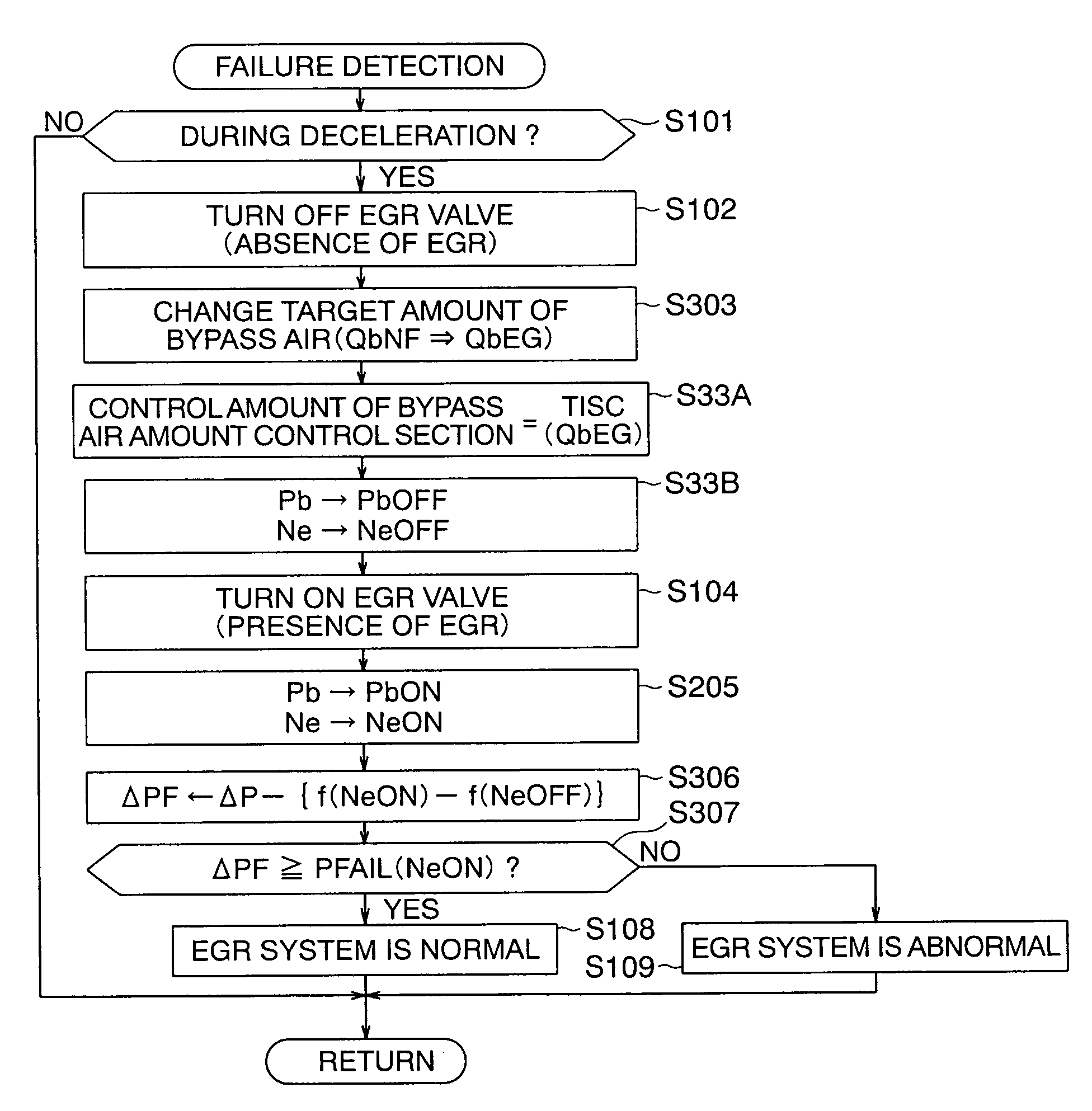
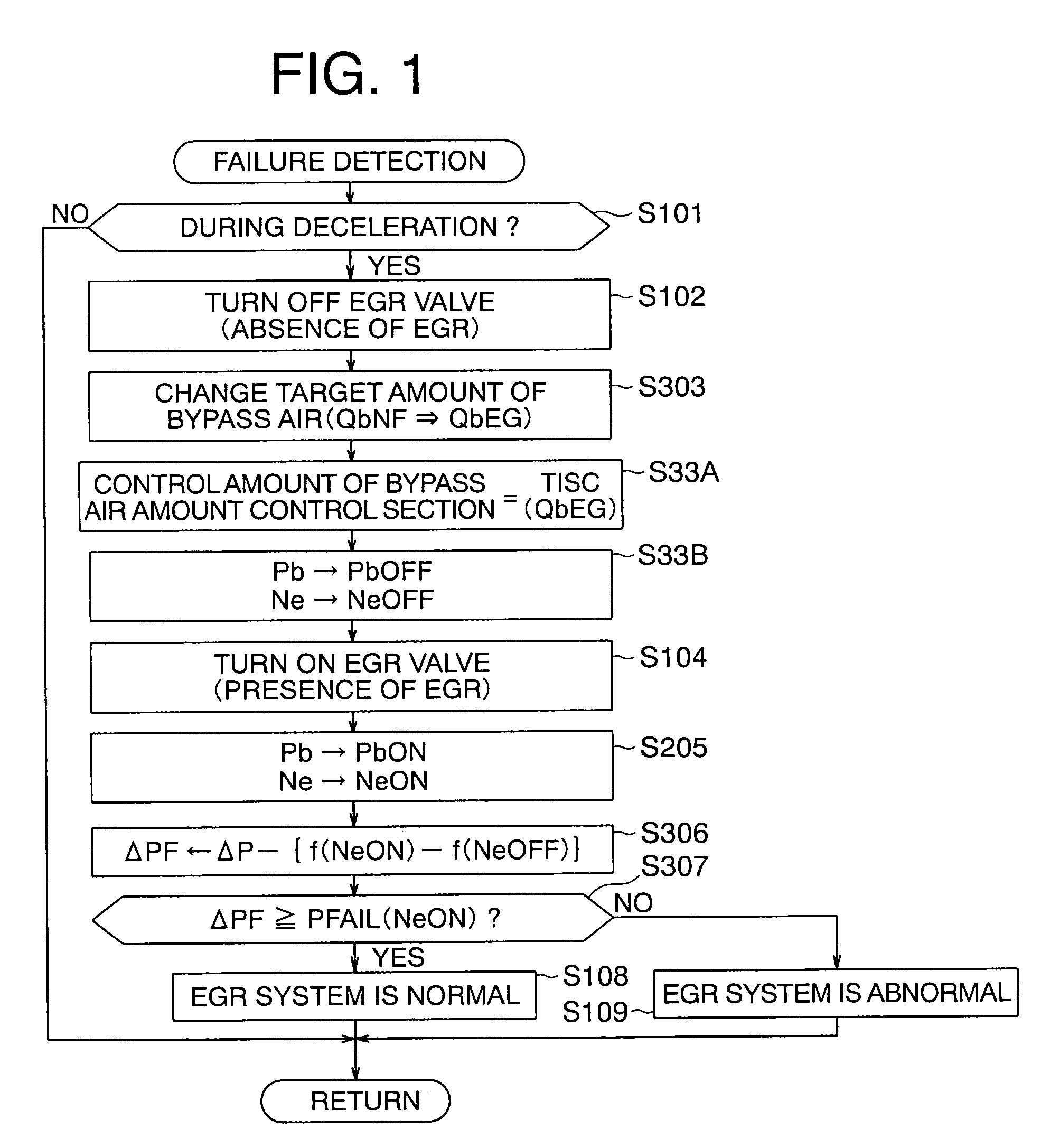
[0105]Here, note that the overall configuration of a system related to a first embodiment of the present invention is as shown in FIG. 8, but only a part of failure detection processing executed in an electronic control unit 22 is different from the above-mentioned one.
[0106]That is, as shown in FIG. 8, a control apparatus for an internal combustion engine according to the first embodiment of the present invention includes a throttle valve 7 that is arranged in an intake pipe 3 so as to be opened and closed to adjust an amount of air Qa supplied to an engine 1 through the intake pipe 3, a bypass air amount control section 9 that controls an amount of bypass air Qb flowing while bypassing the throttle valve 7, an EGR (exhaust gas recirculation) tube 11 that serves to recirculate an exhaust gas exhausted from the engine 1 to a portion of the intake pipe 3 downstream of the throttle valve 7, an EGR valve 12 that adjusts the flow rate of EGR Qe of the exhaust gas flowing through the EGR...
embodiment 2
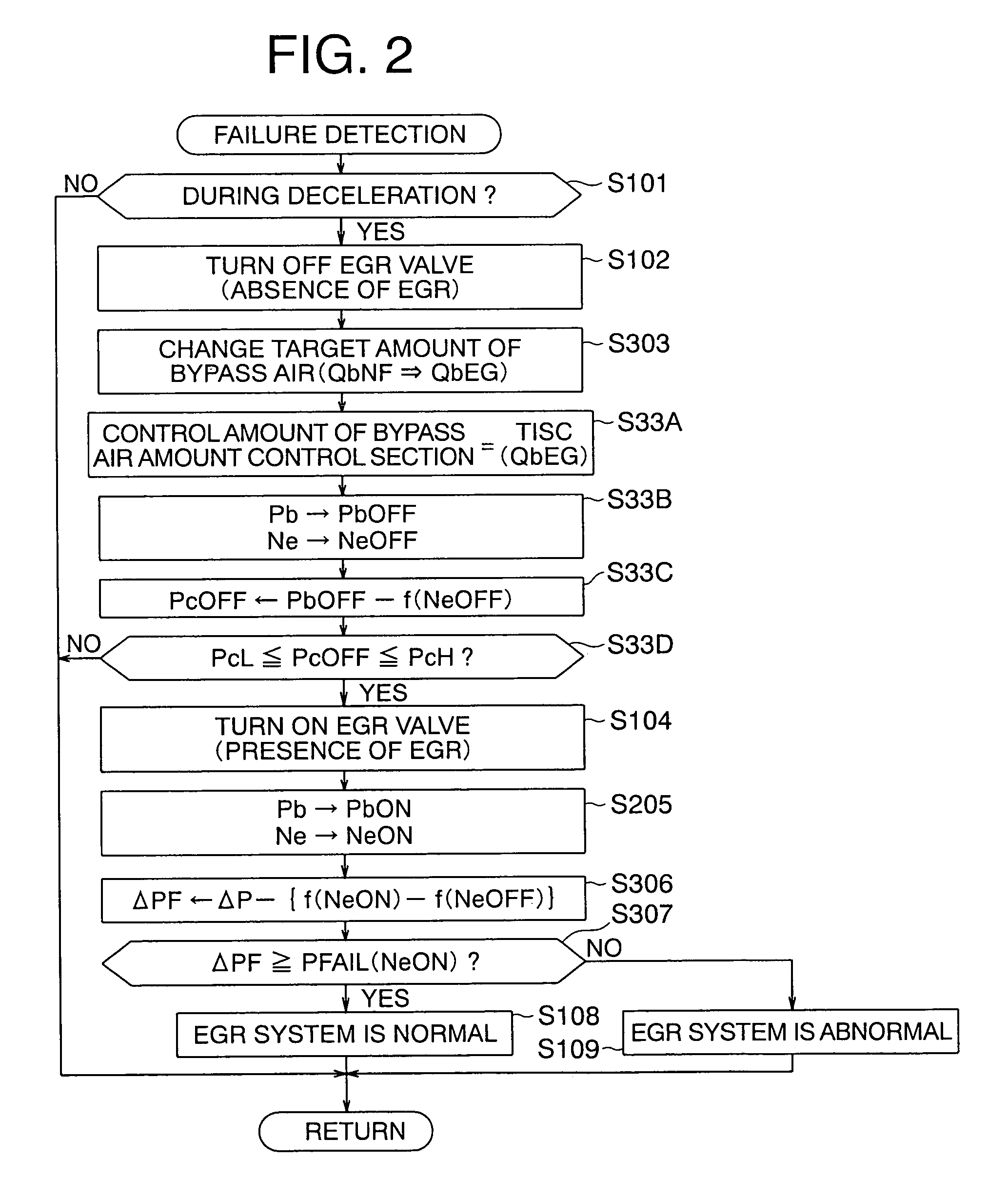
[0154]In the above-mentioned first embodiment (FIG. 1), by only adjusting the bypass air amount control section 9 to the control amount TISC(QbEG) based on the target amount of bypass air QbEG (step S33A), the failure determination condition is assumed to be satisfied (the intake pipe pressure Pb being within the predetermined range), and the pressure difference ΔPF based on the detected value is calculated, but whether the failure determination condition is satisfied may be determined by using a predetermined range calculated based on the number of revolutions per minute of the engine Ne.
[0155]Hereinafter, reference will be made to a second embodiment of the present invention while referring to a flow chart in FIG. 2 together with FIG. 8.
[0156]FIG. 2 illustrates a failure detection processing operation executed in the electronic control unit 22, in which processes similar to the above-mentioned ones (FIG. 1) are identified by the same symbols as above.
[0157]In this case, the electr...
embodiment 3
[0167]In the above-mentioned second embodiment (FIG. 2), when the corrected reference intake pipe pressure PcOFF does not satisfy a permission condition (within a predetermined range) even if the bypass air amount control section 9 is driven by the control amount TISC(QbEG) based on the target amount of bypass air QbEG corresponding to the predetermined state of the intake pipe pressure (the failure determination condition being satisfied), the failure detection processing is terminated (interrupted) at once, but the target amount of bypass air QbEG for EGR failure determination may instead be corrected in a feedback manner until the permission condition is satisfied.
[0168]Hereinafter, reference will be made to a third embodiment of the present invention while referring to flow charts in FIGS. 3 and 4 together with FIG. 8.
[0169]FIG. 3 illustrates a failure detection processing operation executed in the electronic control unit 22, in which processes similar to the above-mentioned one...
PUM
Abstract
A control apparatus for an internal combustion engine can compensate for a variation of intake pressure resulting from various factors whereby a failure detection area can be expanded, and false detection can be prevented to enable failure determination for an EGR system with high reliability. The apparatus determines whether a vehicle is decelerating, forcedly opens and closes an EGR valve, and determines whether an EGR control device is in failure by comparing a pressure change index value based on intake pressures upon the forced opening and closing of the EGR valve with a failure determination value. The apparatus adjusts the intake pressure to a predetermined state before the EGR valve is forcedly opened and closed, whereby a failure determination can be always made based on the intake pressure whose variation was compensated for with the intake pressure becoming a predetermined characteristic to the number of revolutions per minute of the engine.
Description
BACKGROUND OF THE INVENTION[0001]1. Field of the Invention[0002]The present invention relates to a control apparatus for an internal combustion engine (hereinafter referred to as an engine) equipped with a failure detection device for an exhaust gas recirculation control system (EGR system), and more particularly, it relates to a new technique that is capable of preventing the false detection of failure of such an EGR system.[0003]2. Description of the Related Art[0004]In the past, in engine control apparatuses mounted on motor vehicles or the like, there have been proposed a variety of exhaust gas recirculation (EGR) control devices in which a part of an exhaust gas is recirculated into an intake pipe of an engine so as to reduce the combustion temperature of the engine thereby to suppress NOx components in the exhaust gas (see, for instance, a first patent document (Japanese patent application laid-open No. H8-28364) and a second patent document (Japanese patent application laid-o...
Claims
Application Information
Patent Timeline
Application Date:The date an application was filed.
Publication Date:The date a patent or application was officially published.
First Publication Date:The earliest publication date of a patent with the same application number.
Issue Date:Publication date of the patent grant document.
PCT Entry Date:The Entry date of PCT National Phase.
Estimated Expiry Date:The statutory expiry date of a patent right according to the Patent Law, and it is the longest term of protection that the patent right can achieve without the termination of the patent right due to other reasons(Term extension factor has been taken into account ).
Invalid Date:Actual expiry date is based on effective date or publication date of legal transaction data of invalid patent.

