Air-fuel ratio control system for internal combustion engine

a technology of air-fuel ratio and control system, which is applied in the direction of electric control, machines/engines, mechanical equipment, etc., can solve the problems of imbalance in air-fuel ratio, rt accuracy, and the inability to accurately determine the failure of the imbalance, so as to improve the range of calculated determination parameter values, reduce the range of calculation parameter values, and improve the effect of determination accuracy

Active Publication Date: 2014-05-20
HONDA MOTOR CO LTD
View PDF6 Cites 0 Cited by
  • Summary
  • Abstract
  • Description
  • Claims
  • Application Information

AI Technical Summary

Benefits of technology

[0008]The present invention was made contemplating the above described point, and an objective of the present invention is to provide an air-fuel ratio control system which can perform the imbalance failure determination of air-fuel ratios with high accuracy regardless of the imbalance degree.

Problems solved by technology

Accordingly, the determination accuracy may deteriorate depending on the imbalance degree of the actual air-fuel ratio.
The imbalance in the air-fuel ratios occurs, for example, when any one of the fuel injection valves disposed in the plurality of cylinders fails.
Accordingly, in the example shown in FIG. 13A, accuracy of the ratio parameter RT in the high-degree imbalance state decreases, so that a possibility of incorrect determination becomes higher.

Method used


Image

  • Air-fuel ratio control system for internal combustion engine
  • Air-fuel ratio control system for internal combustion engine
  • Air-fuel ratio control system for internal combustion engine

Examples


first embodiment

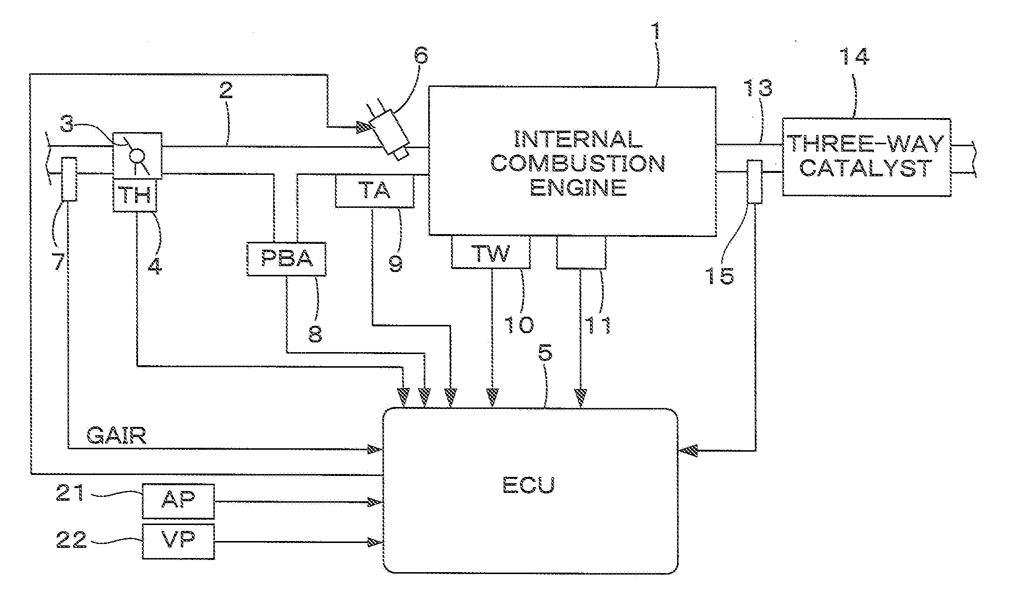
[0037]FIG. 1 is a schematic diagram showing a general configuration of an internal combustion engine (hereinafter referred to as “engine”) and an air-fuel ratio control system therefor, according to one embodiment of the present invention. The engine is, for example, a four-cylinder engine 1 having an intake pipe 2 provided with a throttle valve 3. A throttle valve opening sensor 4 for detecting a throttle valve opening TH is connected to the throttle valve 3, and the detection-signal is supplied to an electronic control unit 5 (hereinafter referred to as “ECU”).

[0038]Fuel injection valves 6 are inserted into the intake pipe 2 at locations intermediate between the cylinder block of the engine 1 and the throttle valve 3 and slightly upstream of the respective intake valves (not shown). These fuel injection valves 6 are connected to a fuel pump (not shown) and electrically connected to the ECU 5. A valve opening period of each fuel injection valve 6 is controlled by a signal output fr...

second embodiment

[0086]FIG. 6 shows a configuration of an internal combustion engine and an air-fuel ratio control system according to the second embodiment of the present invention. The air-fuel ratio control system shown in FIG. 6 is obtained by adding a binary type oxygen concentration sensor (hereinafter referred to as “O2 sensor”) 16 disposed downstream of the three-way catalyst 14 in the system of FIG. 1. The detection signal of the O2 sensor 16 is supplied to the ECU 5. This embodiment is the same as the first embodiment except for the points described below.

[0087]The O2 sensor 16 has a characteristic such that the sensor output VO2 rapidly changes when the air-fuel ratio AF is in the vicinity of the stoichiometric ratio AFST. Specifically, the O2 sensor output VO2 is high if the air-fuel ratio AF is richer than the stoichiometric ratio AFST, whereas VO2 is low if the air-fuel ratio AF is leaner than the stoichiometric ratio AFST.

[0088]In this embodiment, the LAF feedback control is performed...

modification 1

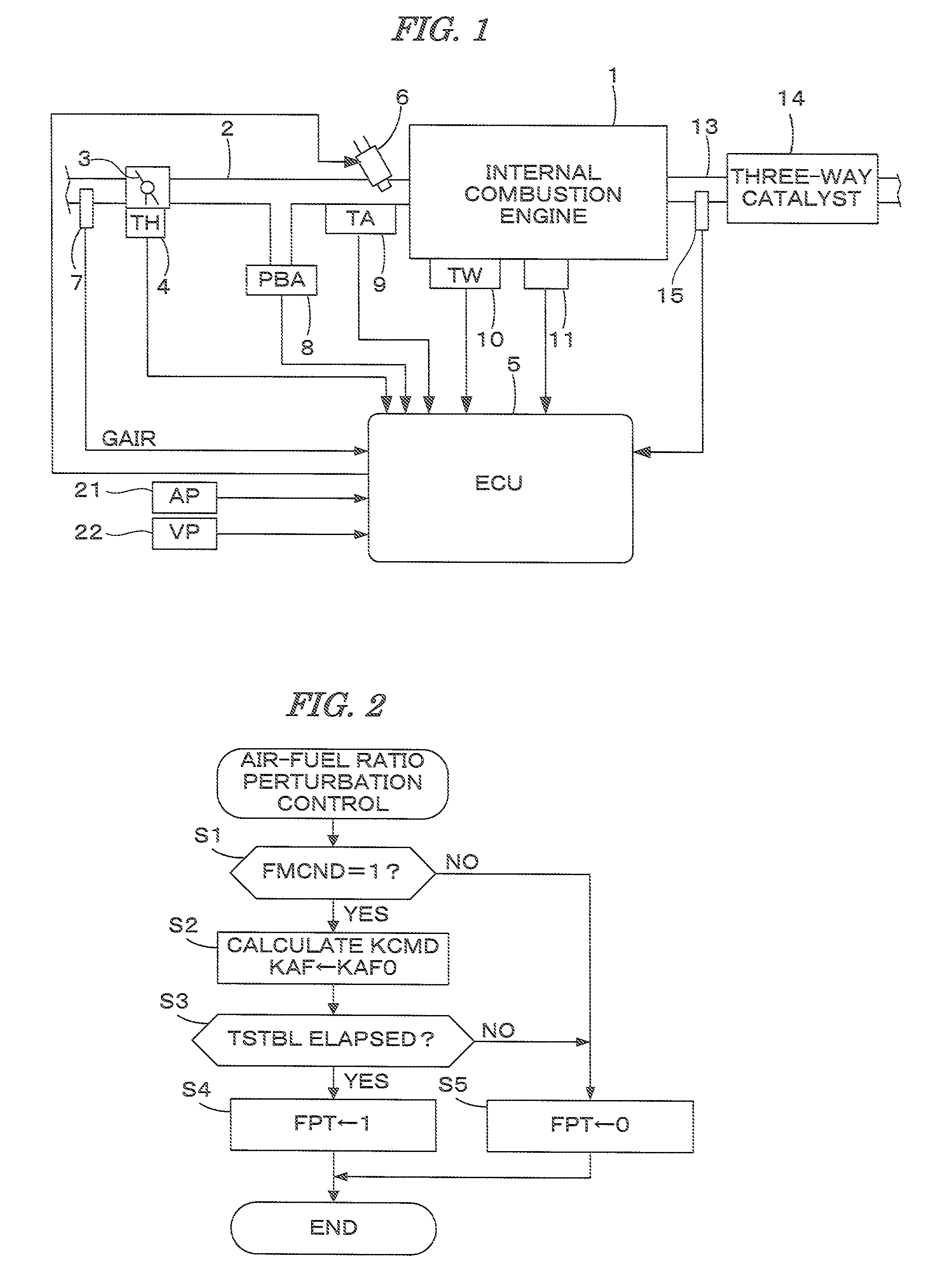
[0103]In this embodiment, the air-fuel ratio perturbation control may be performed by the process shown in FIG. 12 instead of the process of FIG. 2. The process of FIG. 12 is obtained by adding step S1a to the process of FIG. 2.

[0104]In step S1a, the DAF table of FIG. 11 is retrieved according to the adaptive law control input UADP to calculate the amplitude DAF. The process thereafter proceeds to step S2.

[0105]The adaptive law control input UADP is calculated during the normal control in which the imbalance failure determination is not performed. Accordingly, by calculating the amplitude DAF according to the adaptive law control input UADP when the execution condition of the imbalance failure determination is satisfied, and performing the air-fuel ratio perturbation control using the calculated amplitude DAF, the air-fuel ratio perturbation control can be performed more appropriately.

[0106]In this modification, step S1a of FIG. 12 corresponds to the amplitude setting means.


PUM


Abstract

An oscillation signal is generated to oscillate the air-fuel ratio with a set frequency which is different from a 0.5th-order frequency (half of the frequency corresponding to a rotational speed of the engine). Air-fuel ratio perturbation control is performed to oscillate the air-fuel ratio according to the oscillation signal. An intensity of the 0.5th-order frequency component and the set frequency component contained in the detected air-fuel ratio signal are calculated. A determination parameter applied to determining an imbalance degree of air-fuel ratios corresponding to the plurality of cylinders is calculated according to the two intensities and determines an imbalance failure that the imbalance degree of the air-fuel ratios exceeds an acceptable limit. A predicted imbalance value, indicative of a predicted value of the imbalance degree, is calculated, and an amplitude of the oscillation signal is set according to the predicted imbalance value.

Description

BACKGROUND OF THE INVENTION[0001]1. Field of the Invention[0002]The present invention relates to an air-fuel ratio control system for an internal combustion engine having a plurality of cylinders, and particularly to a control system which can determine an imbalance failure that air-fuel ratios corresponding a plurality of cylinders in the engine differ with each other more greatly than the allowable limit.[0003]2. Description of the Related Art[0004]Japanese Patent Laid-open Publication No. 2011-144754 (JP-'754) discloses an air-fuel ratio control system which can determine the imbalance failure based on the output signal of the air-fuel ratio sensor disposed in the exhaust system of the engine. According to this system, the air-fuel ratio perturbation control is performed during the engine operation for oscillating the air-fuel ratio with a predetermined frequency, and the imbalance failure is determined using a ratio parameter which is obtained during the perturbation control. Th...

Claims


Application Information

Patent Timeline
Patent Type & Authority Patents(United States)
IPC IPC(8): F02D41/00F01N3/08
CPCF02D41/1408F02D41/0085F02D2041/288F02D41/1455
Inventor SEKIGUCHI, TOORUMIYAUCHI, ATSUHIROAOKI, TAKESHITANI, MICHINORIWATANABE, SEIJI
Owner HONDA MOTOR CO LTD
Why Eureka
Try Eureka