Seat belt device

a seat belt and seat belt technology, applied in the direction of process and machine control, instruments, pedestrian/occupant safety arrangement, etc., can solve the problem that the passenger cannot be restrained by a seat belt, and achieve the effect of reducing cost and increasing reliability of seat belt device 10

Active Publication Date: 2015-07-30
HONDA MOTOR CO LTD
View PDF1 Cites 0 Cited by
  • Summary
  • Abstract
  • Description
  • Claims
  • Application Information

AI Technical Summary

Benefits of technology

[0063]As thus far described, according to the seat belt device 10 of Embodiment 1, the ECU 100 (failure determining part 120) determines whether the electric brush motor 31 has failed or not on the basis of the presence or absence of a voltage having a frequency component caused by drive control of the electric brush motor 31 that is detected by the voltage detecting part 400 while the electric brush motor 31 is driven by the motor control part 110. With this arrangement, failure diagnosis is possible to perform in any timing as long as the electric brush motor 31 is being driven. This means that failure detection for the electric brush motor 31 can be conducted at increased frequency, and motor failure determination can be appropriately performed. It is therefore possible to avoid occurrence of an unwanted condition where the passenger cannot be restrained by the seat belt device due, for example, to a motor failure occurring when an emergency condition happens on the vehicle. The reliability of the seat belt device 10 can thus be increased.
[0064]According to the seat belt device 10 of Embodiment 1, the ECU 100 (failure determining part 120) determines whether the electric brush motor 31 has failed or not when the vehicle state detecting part 500 detects an action to fit the webbing 16 or an action to take up a slack of the webbing 16 in a condition where acceleration equal to or more than a predetermined value is not generated on the vehicle (comfort mode). With this arrangement, it is possible to prevent the electric brush motor 31 from being driven with a large current which would otherwise occur when the vehicle is in the pre-crash state. Furthermore, the ECU 100 (failure determining part 120) filters a ripple voltage detected by the voltage detecting part 400 and determines whether the electric brush motor 31 has failed or not on the basis of a waveform of the filtered voltage. With this arrangement, a failure diagnosis can be achieved at a reduced cost.

Problems solved by technology

Due to a relatively few motor-failure detection opportunities, it may occur that a passenger cannot be restrained by a seat belt due to a motor failure occurring when an emergency condition happens on the vehicle.

Method used


Image

  • Seat belt device
  • Seat belt device
  • Seat belt device

Examples


embodiment 1

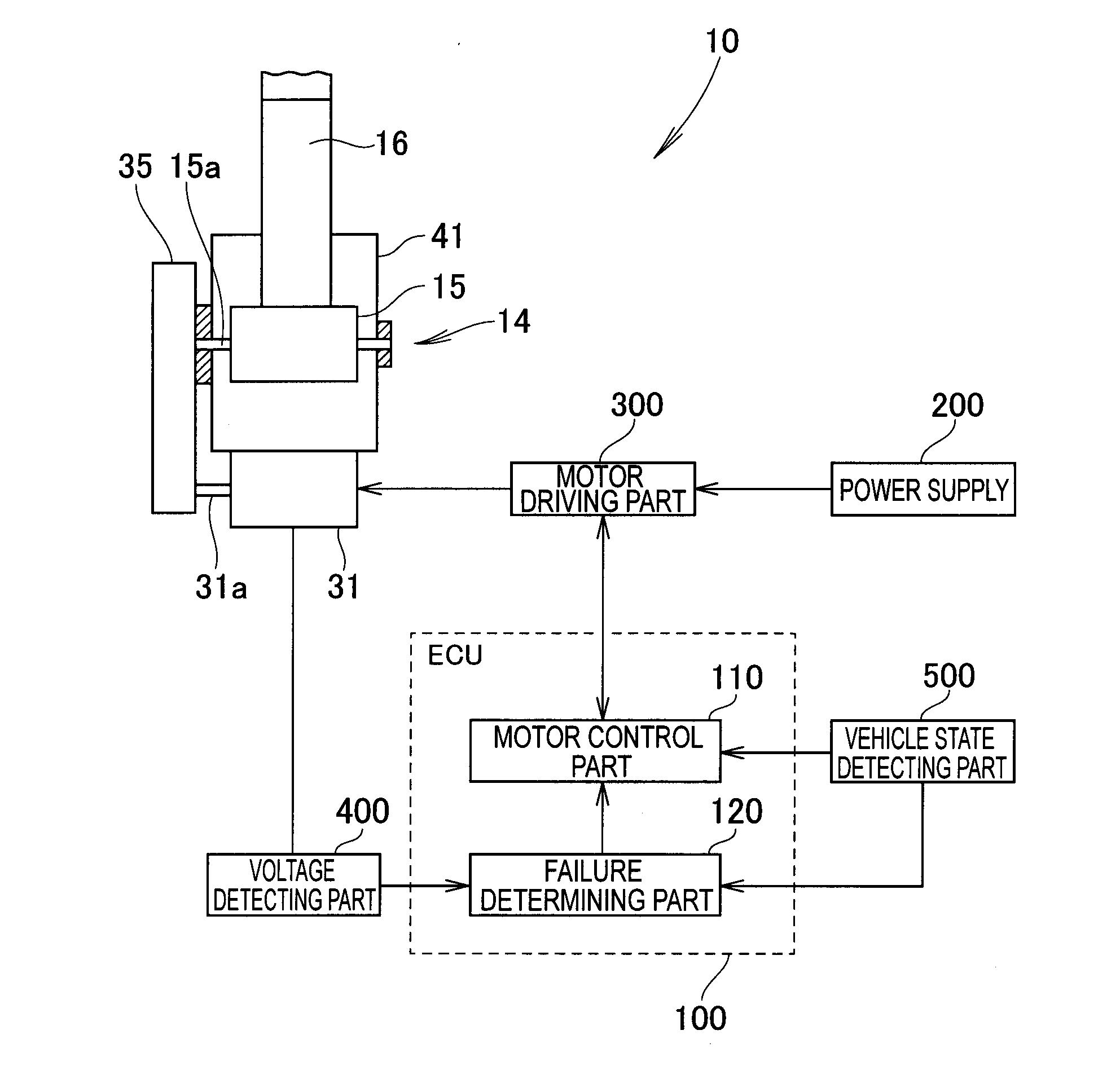
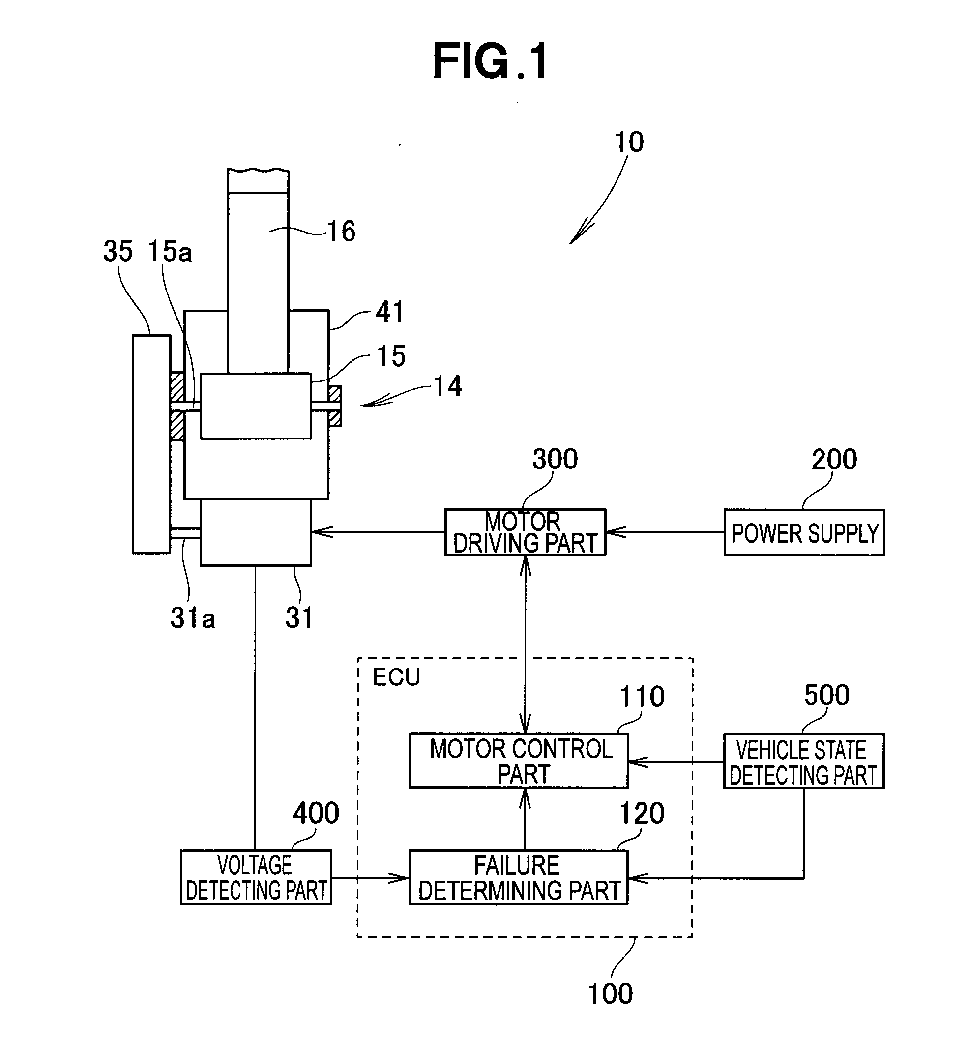
[0053]FIG. 8 is a flowchart showing a failure diagnosing process for the electric brush motor 31 according to Embodiment 1. In FIG. 8, the motor control part 110 of the ECU 100 first determines an operation mode of the vehicle based on an output from the vehicle state detecting part 500. More specifically, it is determined whether the vehicle is operating in a comfort mode in which the buckle has shifted from a non-fitted state to a fitted state and an action to take up a slack of the webbing has been detected in a condition where acceleration equal to or more than a predetermined value is not generated on the vehicle (Step S101).

[0054]When the motor control part 110 determines that the vehicle is operating in the comfort mode (“YES” determination in Step S101), the failure determining part 120 receives a terminal voltage of the electric brush motor 31 measured by the voltage detecting part 400 (Step S102) and determines the presence or absence of a ripple noise on the basis of a wa...

embodiment 2

[0065]FIG. 10 is a flowchart showing a failure diagnosing process for the electric brush motor 31 according to Embodiment 2. The motor control part 110 of the ECU 100 first determines an operation mode of the vehicle based on an output from the vehicle state detecting part 500 in the same manner as in Embodiment 1 (Step S201). When the motor control part 110 determines that the vehicle is operating in a comfort mode in which the buckle has shifted from a non-fitted mode to a fitted mode and an action to take up a slack of the webbing has been detected in a condition where acceleration equal to or more than a predetermined value is not generated on the vehicle (“YES” determination in Step S201), the failure determining part 120 receives a terminal voltage of the electric brush motor 31 measured by the voltage detecting part 400 (Step S202) and determines the presence or absence of a ripple noise on the basis of a waveform of the received terminal voltage (Step S203). The ripple-noise...


PUM


Abstract

A seat belt device includes a belt reel on which a webbing is wound, an electric brush motor for driving the belt reel, a motor control part that performs drive control of the electric brush motor, a voltage detecting part that detects a voltage generated between both terminals of the electric brush motor, and a failure determining part that determines whether the electric brush motor has failed or not on the basis of the presence or absence of a voltage having a frequency component caused by the drive control of the electric brush motor that is detected by the voltage detecting part while the electric brush motor is driven by the motor control part.

Description

FIELD OF THE INVENTION[0001]The present invention relates to an improvement in a seat belt device.BACKGROUND OF THE INVENTION[0002]Japanese Patent Application Laid-open Publication (JP-A) No. 2003-160024 discloses a seat belt device configured to enable a passenger to confirm a failure occurring in a pretensioner motor and the like. The disclosed seat belt device includes a motor, a motor driving means, a driving force transmitting means, and a failure determining means. The failure determining means determines the presence or absence of a motor failure on the basis of a current waveform generated when the motor driving means drives the motor while the driving force transmitting means interrupts transmission of a driving force from the motor to a seat belt wind-up device.[0003]In the seat belt device shown in JP 2003-160024 A, detection of a motor failure is started and performed when an ignition switch is turned on, when a driver's-side door switch is turned on, or when depression ...

Claims


Application Information

Patent Timeline
Patent Type & Authority Applications(United States)
IPC IPC(8): B60R21/017H02P7/28
CPCB60R21/017B60R2021/01184B60R2021/01286H02P7/28B60R22/46B60R2022/4666H02P29/02H02P6/007
Inventor ODATE, SHOTARO
Owner HONDA MOTOR CO LTD
Why Eureka
Try Eureka