Sample carrier having sample tube blocking member

a sample carrier and blocker technology, applied in the field of sample carriers, can solve the problems of removing the seal which exerts too great retention force against the fluid transfer device, and achieves the effect of minimizing the chance of contaminating the sample carrier and its contents

Active Publication Date: 2007-10-02
GEN PROBE INC
View PDF150 Cites 112 Cited by
  • Summary
  • Abstract
  • Description
  • Claims
  • Application Information

AI Technical Summary

Benefits of technology

[0021]In another embodiment of the present invention, a drip shield is provided for use in an automated sampling system to protect the contents of sample tubes held by sample carriers from fluid contamination, especially hanging droplets which may be dislodged from a robotic pipetting device during an automated sampling procedure. By “automated sampling system” is meant a system for holding a sample tube in a substantially vertical orientation and conveying the sample tube by automated means to a location within an apparatus where the contents of the sample tube may be accessed by a robotic pipetting device in order to effect a transfer of at least a portion of the contents to another location within the apparatus. The drip shield of the present invention is preferably constructed of a substantially non-conductive material and includes a cover plate which may have an arcuate shape conforming to the arcuate shape of the preferred sample carrier.
[0022]The cover plate of the drip shield includes one or more through-holes, where each through-hole is configured and arranged to provide non-interfering, vertical passage of an aligned pipette tip therethrough. The through-holes are sized to permit access to the contents of only one sample tube at a time, where the sample tubes being accessed are present in a sample carrier positioned beneath the cover plate. In a preferred embodiment, the diameter of each through-hole is the same as or smaller than the smallest diameter of any sampl

Problems solved by technology

What these sample carriers lack, however, is a mechanism for ensuring that sample tubes remain in the sample carriers during automated sampling procedures when the retention force of a cap is greater than the holding force of the sample carrier on an associated ve

Method used


Image

  • Sample carrier having sample tube blocking member
  • Sample carrier having sample tube blocking member
  • Sample carrier having sample tube blocking member

Examples


Embodiment Construction

[0054]While the present invention may be embodied in a variety of forms, the following description and accompanying drawings are merely intended to disclose some of those forms as specific examples of the present invention. Accordingly, the present invention is not intended to be limited to the forms or embodiments so described and illustrated. Instead, the full scope of the present invention is set forth in the appended claims.

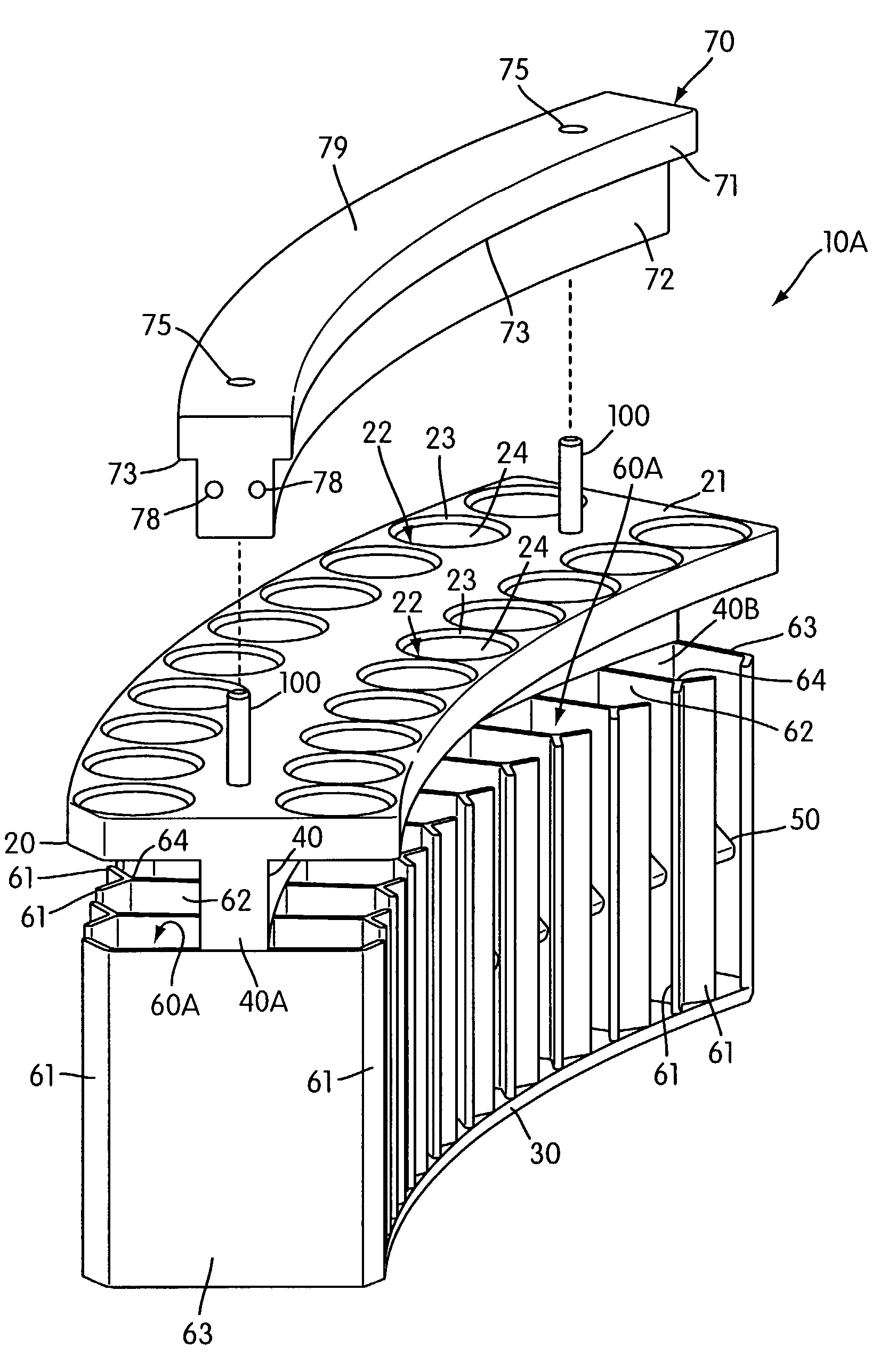
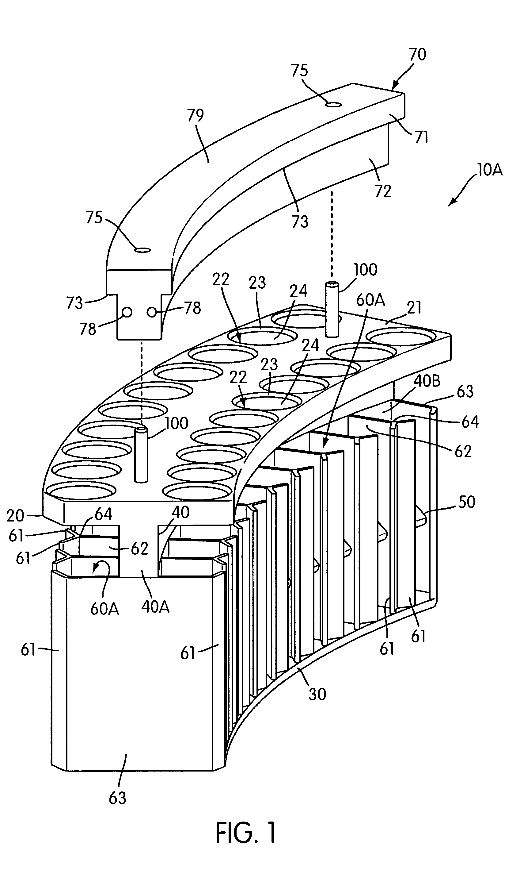
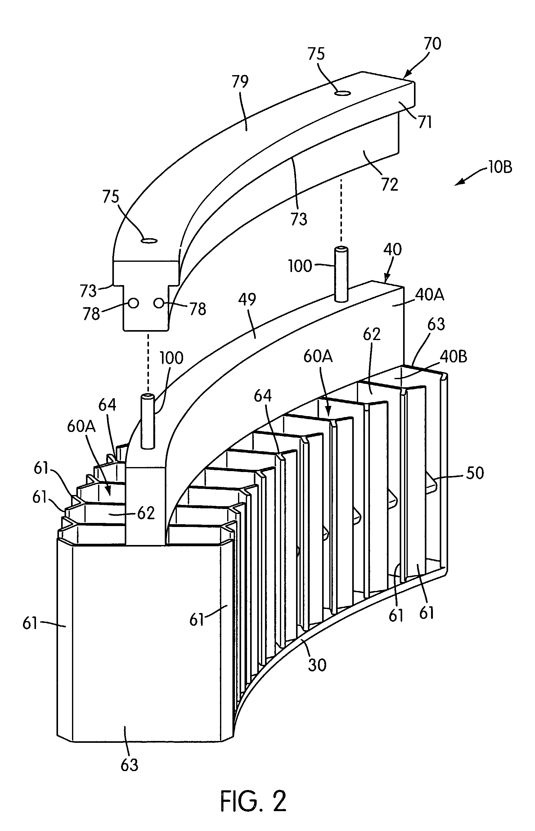
[0055]With reference to the figures, preferred sample carriers 10 of the present invention are shown alone or in combination with a drip shield 200 for protecting against cross-contamination between sample tubes 300 carried by the sample carriers and for limiting vertical movement of the sample carriers when sample is being removed from any of the sample tubes. (Reference herein to a “sample carrier 10” is a general reference of to any of the illustrated sample carriers 10A-D.) Sample carriers 10 of the present invention are preferably used in combination wit...


PUM


Abstract

A sample carrier comprising a lower support wall, a base joined to or in fixed proximity to a bottom end of the lower support wall, and sample tube receiving areas in fixed proximity to the lower support wall for receiving and holding a plurality of sample tubes in substantially vertical orientations. The sample carrier further comprising a blocking wall joined to a top end of the support wall which extends laterally over portions of sample tubes held by the sample carrier, thereby limiting vertical movement of the sample tubes during automated sampling procedures. The contents of sample tubes held by the sample carrier can be accessed by a robotic pipetting device. Additionally, a drip shield comprising a cover plate, a pair of through-holes for accessing sample tubes held by a the sample carrier, and a depending runner for maintaining the sample carrier on a sample carousel.

Description

CROSS-REFERENCE TO RELATED APPLICATIONS[0001]This application claims the benefit of U.S. Provisional Application No. 60 / 381,551, filed May 17, 2002, and U.S. Provisional Application No. 60 / 443,458, filed Jan. 29, 2003, each of which applications is hereby incorporated by reference herein.FIELD OF THE INVENTION[0002]The present invention relates to a sample carrier for holding and containing a plurality of sample tubes. The sample carrier of the present invention is especially suited for use with an automated sampling system and sample tubes having penetrable caps. The present invention further relates to a drip shield for protecting against cross-contamination between sample tubes and for substantially limiting vertical movement of sample carriers positioned on conveying means during an automated sample transfer.INCORPORATION BY REFERENCE[0003]All references referred to herein are hereby incorporated by reference in their entirety. The incorporation of these references, standing alo...

Claims


Application Information

Patent Timeline
IPC IPC(8): B01L9/00B01L3/14G01N35/04B01L9/06G01N35/02
CPCB01L9/06G01N35/025G01N35/10B01L3/50825B01L2200/023B01L2200/025B01L2200/0615B01L2200/141G01N2035/0465B01L2300/041G01N35/1011G01N2035/0448G01N2035/0451B01L2300/021
Inventor SEVIGNY, GERARD J.TALMER, MARK A.WEBB, MATTHEW W.TSEO, GUS G.
Owner GEN PROBE INC
Why Eureka
Try Eureka