Fastener for electrical conduits and tubes

a technology for fasteners and electrical conduits, which is applied in the direction of machine supports, filing appliances, other domestic objects, etc., can solve the problems of increasing the difficulty of laying these materials, and achieve the effects of increasing friction between conduits, increasing the diameter, and increasing the intrinsic weigh

Inactive Publication Date: 2007-10-02
AIRBUS OPERATIONS GMBH
View PDF7 Cites 6 Cited by
  • Summary
  • Abstract
  • Description
  • Claims
  • Application Information

AI Technical Summary

Benefits of technology

[0010]In order to allow an easy mounting of the holder or mount to the beam or bearer, the basic body has a pin for engaging into a corresponding recess or bore in the beam. Preferably, for an easy mounting at the beam, the pin is embodied in such a way that when engaging the recess of the beam, it “remains stuck” and thereby holds the basic body. To this end, it may be sufficient, if the pin holds the intrinsic weight of the basic body at the beam. In a preferable manner, it may thereby be affixed to the beam with one hand, when mounting the basic body. Then, for the final attachment, the holder may be secured at the beam by shifting-in and / or “click-together” the slide-in part with the basic body. Moreover, the pin thereby prevents a relocating of the basic body, as for example an axial relocation.
[0012]In a further exemplary embodiment according to the invention, basic body and slide-in part consist of one material. This material may be synthetics or plastics. For example, the basic body and the slide-in part may be produced by an injection moulding process. Basic body and slide-in part may also be made from synthetics, and at the same time possess an reinforcing structure from metal. In particular, this may be an advantage, if conduits of greater diameter and higher intrinsic weight shall be laid. But basic body and slide-in part may also be from metal, and in addition possess structures made from a synthetic material. For this, the regions in direct contact with the conduits, may be provided with riffles or similar structures of a synthetic material which, with riffles or without, may prevent e.g. a slipping away of the conduits. Also, this may increase a friction between the conduits and the mount and the carrier and the mount. If the basic body and pin are embodied in integral or one-piece manner, there is provided a holder which, in a preferable manner, only has two parts.

Problems solved by technology

If thicker materials are used for higher current, this may lead to the laying of these materials becoming more difficult, since these thicker materials are more difficult to bend or to deform, respectively.

Method used


Image

  • Fastener for electrical conduits and tubes
  • Fastener for electrical conduits and tubes
  • Fastener for electrical conduits and tubes

Examples


Embodiment Construction

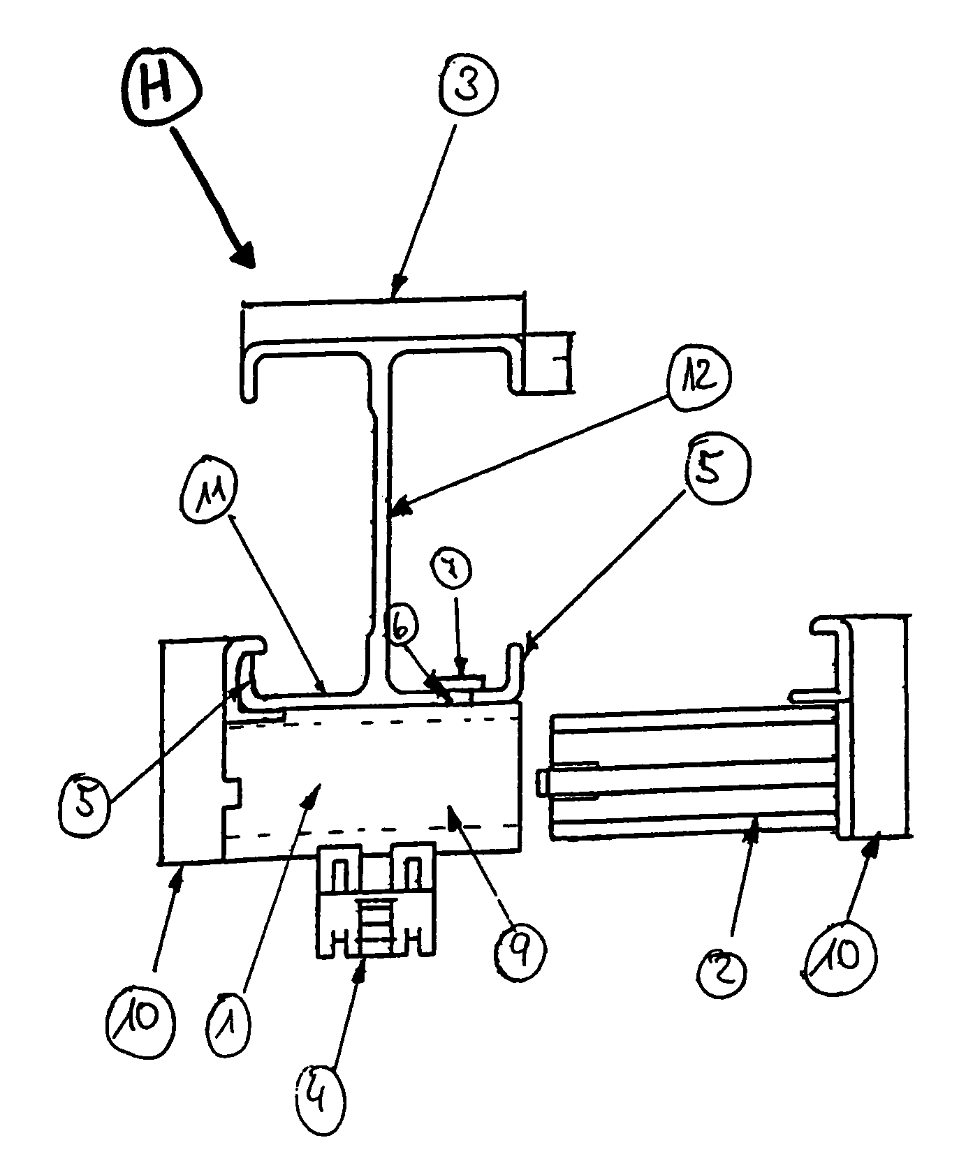
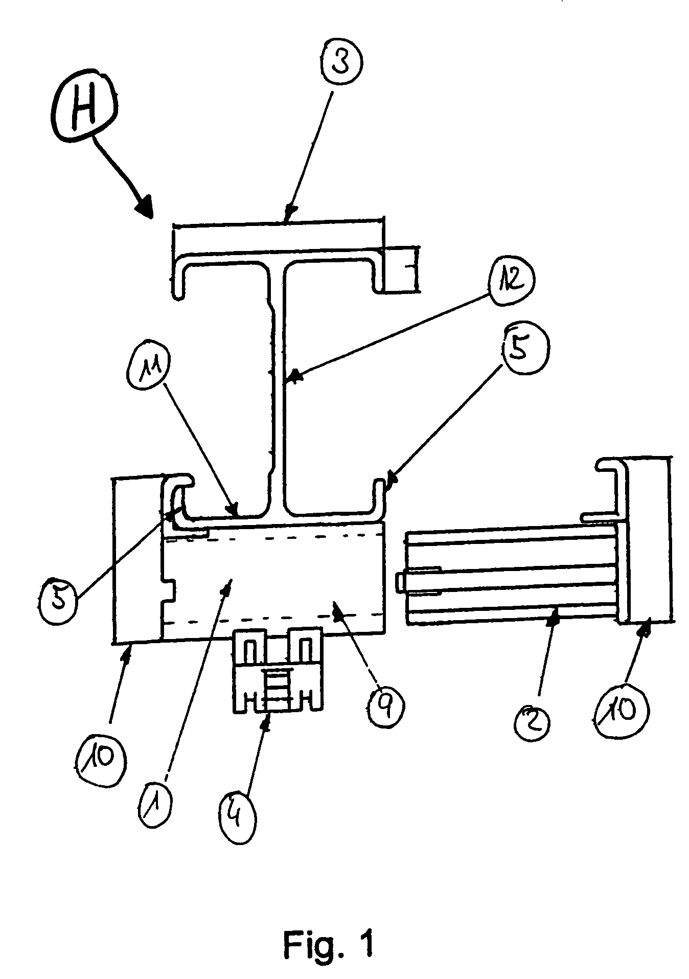
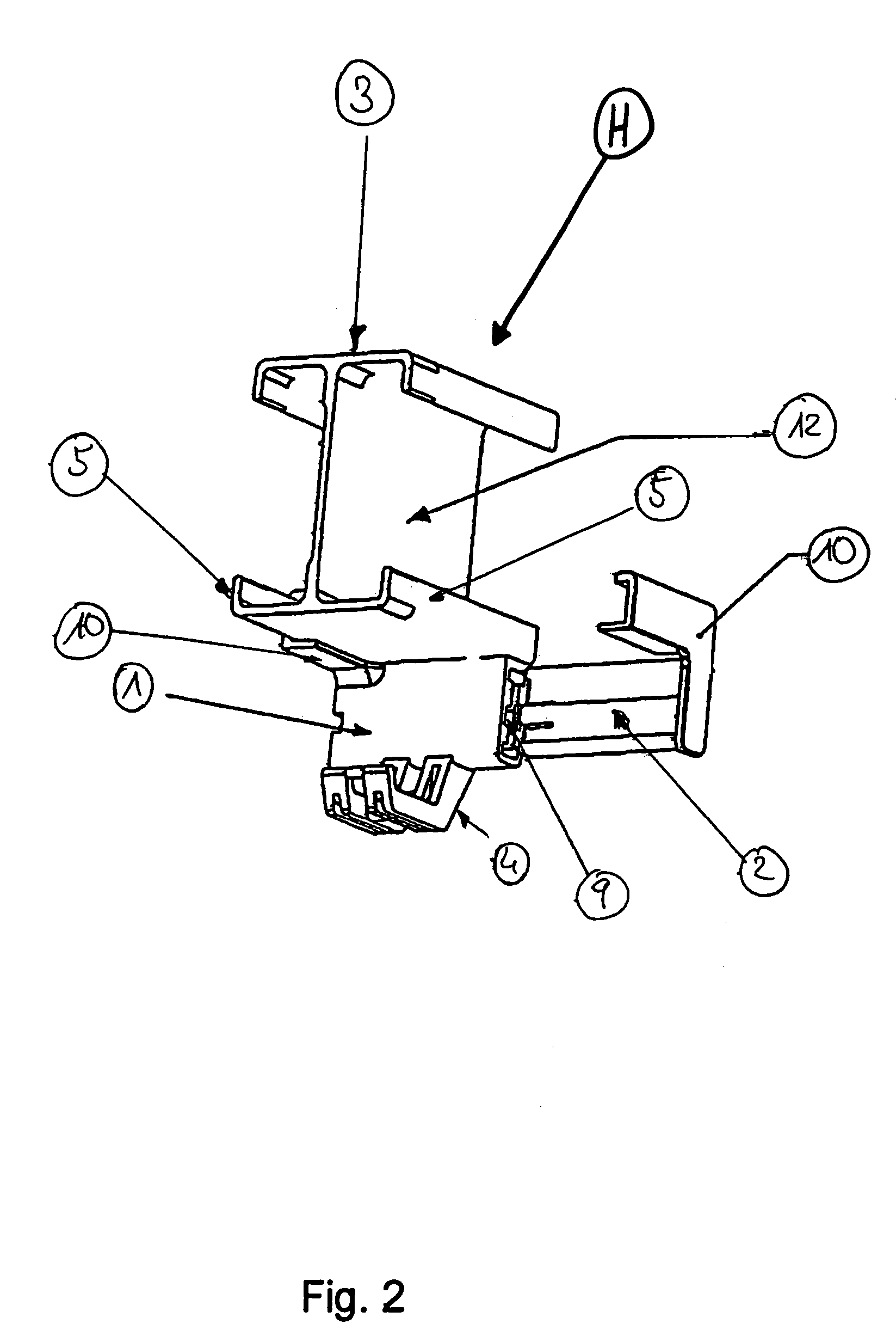
[0021]FIG. 1 shows a front view of a holder H. The holder H is mounted at a beam, for example at a double-T-beam. A double-T-beam comprises two horizontal areas, the belt 11, and an area connecting them usually referred to as the bar 12. Depending on the needs and requirements, the size relationships between belt 11 and bar 12 may vary. Anyway, such beams have an area, for example, the lower horizontal area or the lower belt 11, which may be used for mounting the basic body 1. The lower belt 11 of the carrier has a short vertical area extending upwards at its side turned away from the bar and adjacent to the belt. This short vertical area may also be called bar 5. When mounting, the holder may be applied to the bar 5.

[0022]As shown in FIG. 1, the holder H for mounting electrical conduits at a beam 3, in airplanes, has a basic body 1. The basic body is situated directly at the belt 11 of the beam 3. According to an exemplary embodiment, the basic body 1 and the slide-in part 2 are ma...


PUM


Abstract

A holder for mounting conduits and tubes at a carrier in airplanes, including a basic body and at least one slide-in part. In this context, the basic body has a recess for receiving the slide-in part. The slide-in part is held in an end position in the recess. By means of the slide-in part, the basic body may be disposed at the carrier. The holder is designed to receive conduits and tubes with a diameter in the order of magnitude of 30 to 50 mm thickness.

Description

CROSS-REFERENCE TO RELATED APPLICATIONS[0001]This application claims the benefit of the filing date of U.S. Provisional Patent Application No. 60 / 598,239 filed Aug. 3, 2004, the disclosure of which is hereby incorporated herein by reference.FIELD OF THE INVENTION[0002]The present invention concerns a holder or mount for conduits, conduit routes, lines or cables in an airplane, as well as a corresponding method for mounting the holder.BACKGROUND OF THE INVENTION[0003]For local mounting of at least one conduit at a component, there are known various embodiments of a holder. Holders of this kind are especially used in the aerospace industry to lay conduits, conduit bundles and tubes or cables and lines. In the state of the art, holders for mounting electrical conduits or guiding of electrical conduit bundles, respectively, are used in different fields.[0004]In the state of the art, the holders are mounted at the cross beam or rib by means of screwing. When mounting by means of these ho...

Claims


Application Information

Patent Timeline
Patent Type & Authority Patents(United States)
IPC IPC(8): H02G3/36
CPCB64C1/406H02G3/0456Y10S248/906
Inventor ZEUNER, LUTZPLATE, HANS-GEORGKOSIANKOWSKI, LUEDERGUTHKE, HANS-PETER
Owner AIRBUS OPERATIONS GMBH
Why Eureka
Try Eureka