Payload overload control system

a control system and payload technology, applied in the field of payload overload control system, can solve the problems of machine components such as the lift linkage falling, machine components can wear more quickly, and the payload may exceed the maximum payload

Active Publication Date: 2007-10-02
CATERPILLAR INC
View PDF26 Cites 39 Cited by
  • Summary
  • Abstract
  • Description
  • Claims
  • Application Information

AI Technical Summary

Problems solved by technology

Lifting and carrying payloads above this maximum payload may be dangerous because the excess weight at an elevated position may make the machine unstable, particularly when driving over uneven surfaces.
In addition the machine components such as the lift linkage can fall because they may not be designed to regularly handle payloads in excess of the maximum payload for which the machine is rated.
Even if no immediate harm is manifested by an overload, the machine components can wear more quickly.
However, the desired amount above which the '471 patent will dump material is not a maximum payload for the loader itself, but rather for a hauling vehicle that the loader may be loading.
Therefore, while the system of the '471 patent may prevent overloading of the hauling vehicle, it does nothing to guard against the ill effects of overloading the loader itself.
Further, the system of '471 patent does not prevent lifting of a payload exceeding the maximum rated payload for the loader.

Method used


Image

  • Payload overload control system
  • Payload overload control system
  • Payload overload control system

Examples


Embodiment Construction

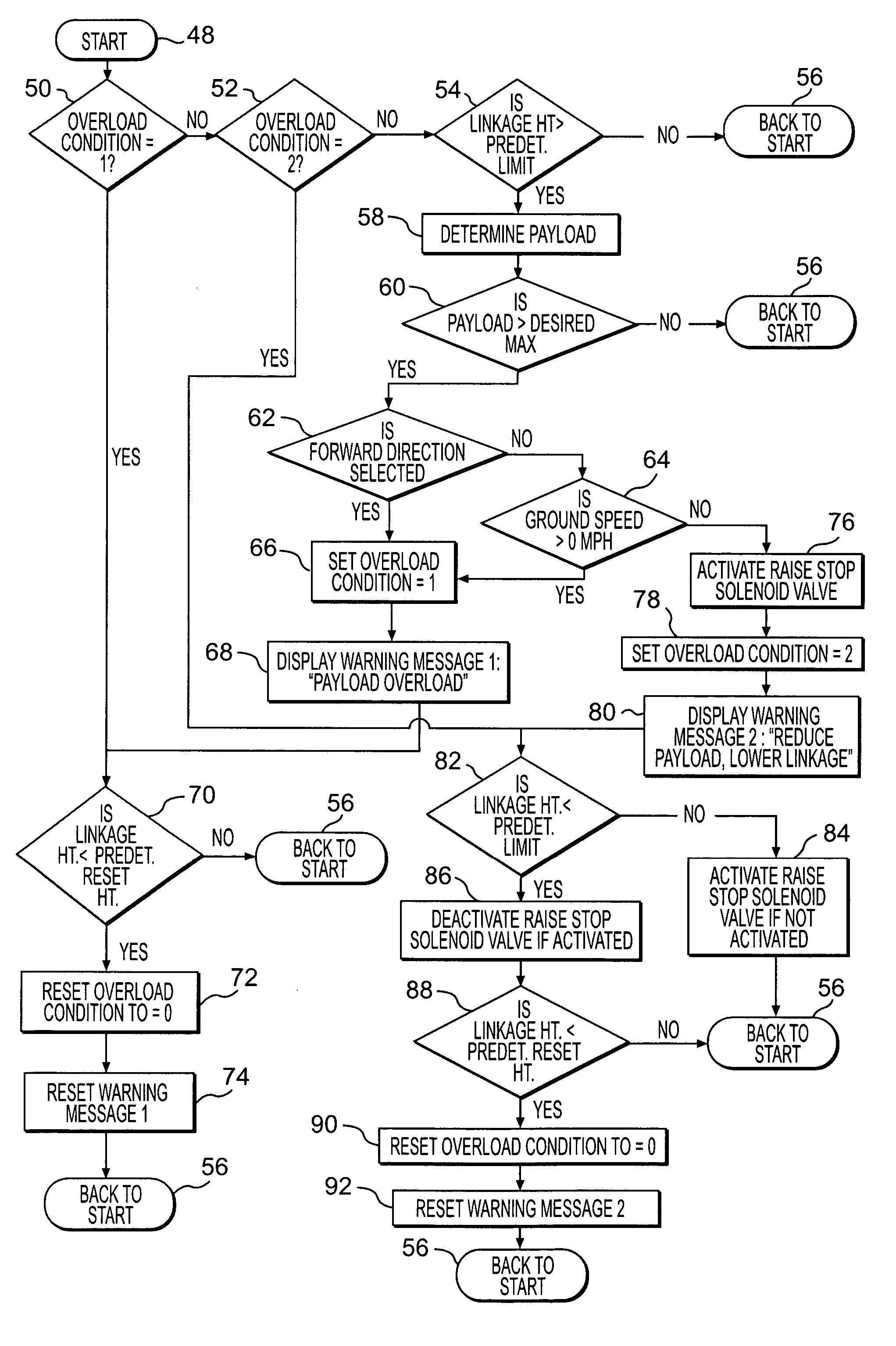
[0010]Reference will now be made in detail to the drawings. Wherever possible, the same reference numbers will be used throughout the drawings to refer to the same or like parts.

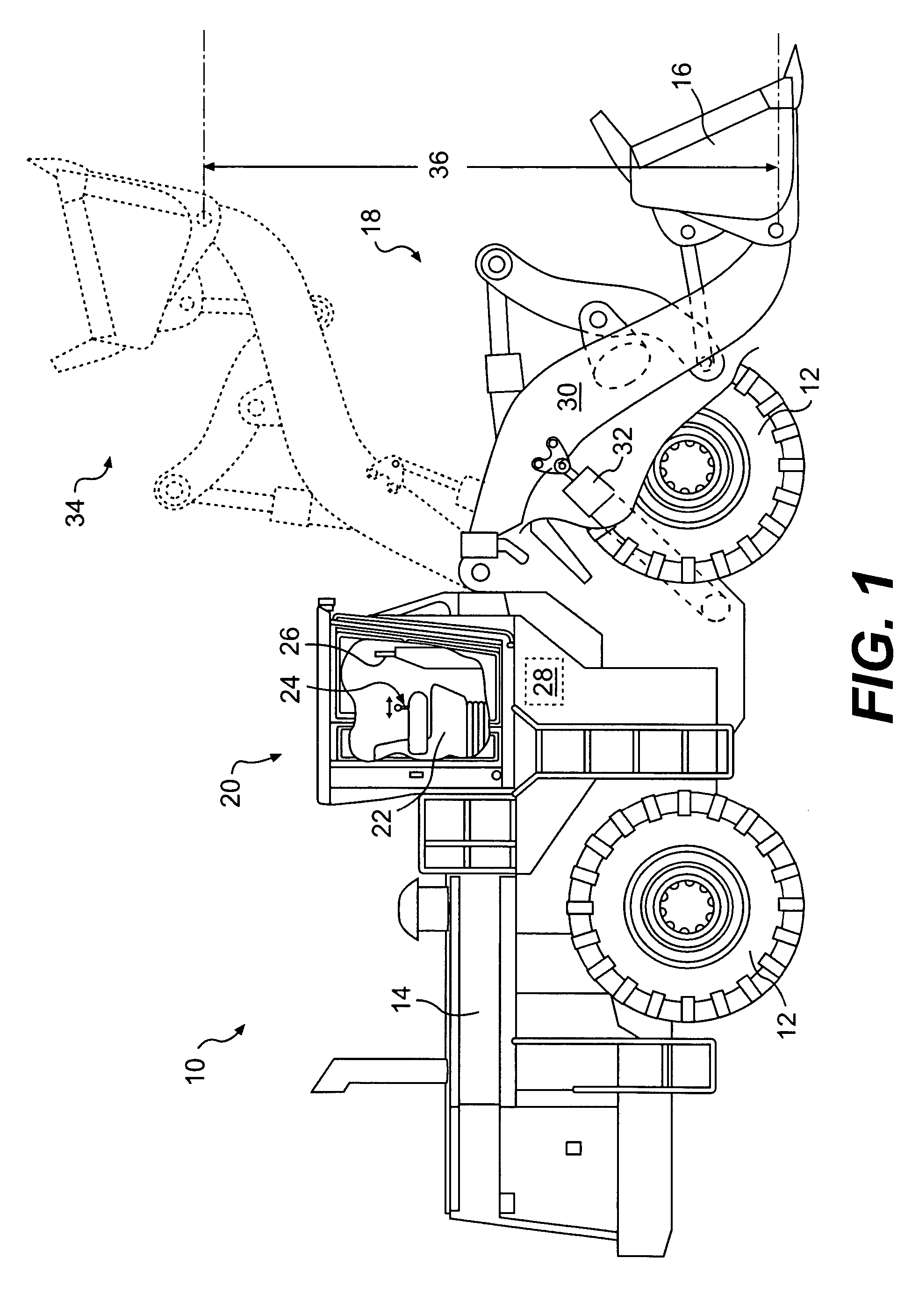
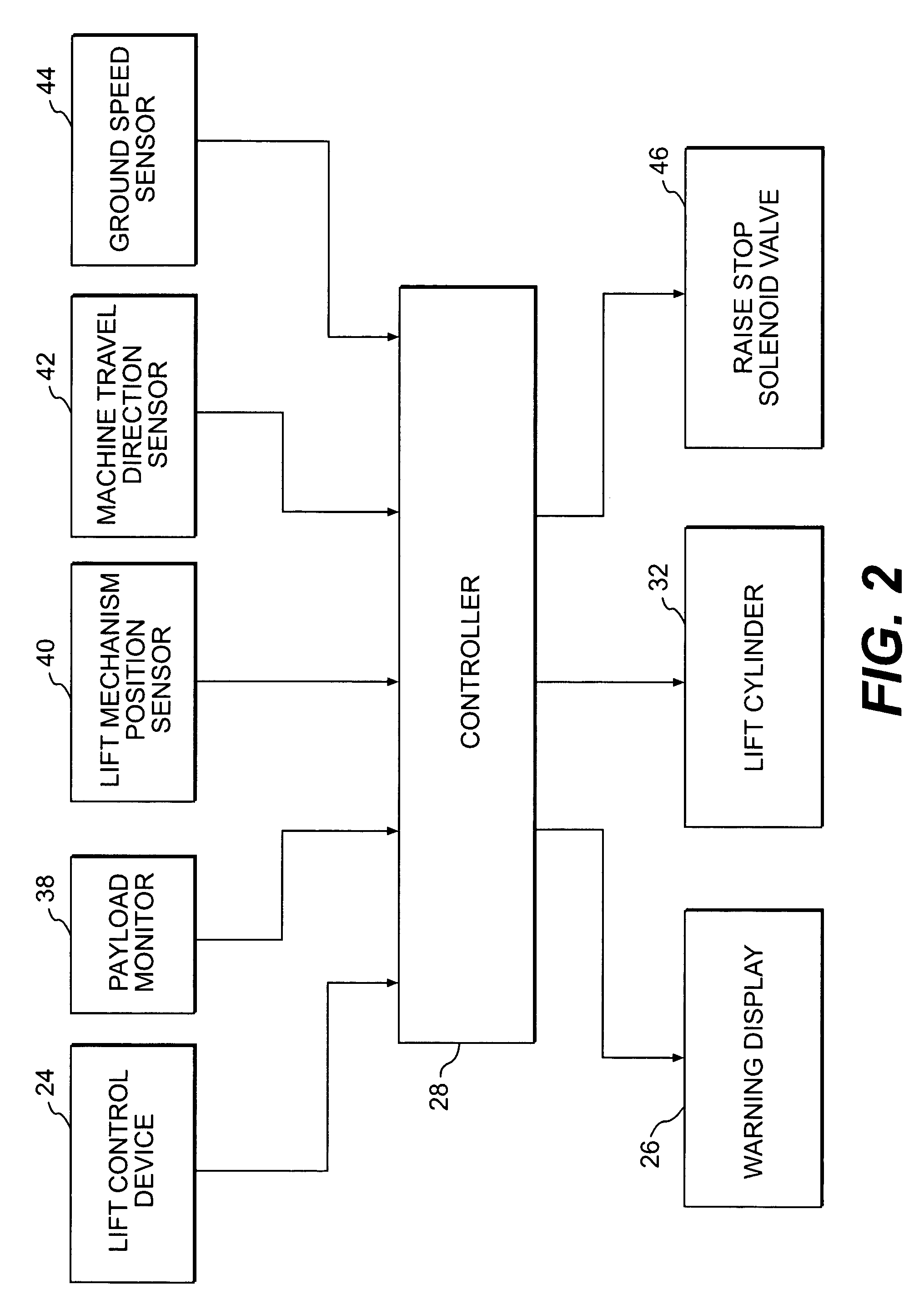
[0011]FIG. 1 shows a work machine 10 having one or more traction devices 12, a power source 14, a payload carrier 16, and a lift mechanism 18. Work machine 10 may further include an operator station 20, which may include an operator seat 22, a lift control device 24, and a warning display 26. Work machine 10 may also include a controller 28.

[0012]Although work machine 10 is shown as a wheel loader, work machine 10 may be any kind of machine configured to lift and carry a payload, such as, for example, track type loaders, forklifts, skid steers, etc. Accordingly, traction devices 12 may be any type of traction devices, such as, for example, wheels, as shown in FIG. 1, tracks, bands, or any combinations thereof.

[0013]Payload carrier 16 may be a bucket, as shown in FIG. 1. Alternatively, payload carrier 16 may ...


PUM


Abstract

A work machine may have a payload overload control system. The system may include a payload carrier and a lift mechanism configured to raise and lower the payload carrier. The system may further include a payload monitor configured to determine a payload in the payload carrier. The system may also include a controller configured to compare the determined payload with a predetermined maximum payload and to selectively control lift of the payload carrier by the lift mechanism based on the comparison between the determined payload and the predetermined maximum payload.

Description

TECHNICAL FIELD[0001]The present disclosure is directed to a payload overload control system, and more particularly to a lift disabling payload overload control system.BACKGROUND[0002]Earthmoving machines such as loaders may be used to move earth, rocks, and other materials from one place to another. These machines may be rated for a particular maximum payload. Lifting and carrying payloads above this maximum payload may be dangerous because the excess weight at an elevated position may make the machine unstable, particularly when driving over uneven surfaces. In addition the machine components such as the lift linkage can fall because they may not be designed to regularly handle payloads in excess of the maximum payload for which the machine is rated. Even if no immediate harm is manifested by an overload, the machine components can wear more quickly.[0003]Systems have been designed to monitor the payload on earthmoving machines. For example, U.S. Pat. No. 6,211,471, issued to Rock...

Claims


Application Information

Patent Timeline
Patent Type & Authority Patents(United States)
IPC IPC(8): G01G19/08G06F17/00
CPCE02F9/2025G01G19/083E02F9/26E02F9/24E02F9/265
Inventor DAHL, KRISTOFOR LEECLER, ERIC WADELI, WEIANELOSKI, RANDY G.
Owner CATERPILLAR INC
Why Eureka
Try Eureka