
Stereo imaging system and method for use in telerobotic systems

a telerobotic system and imaging system technology, applied in the field of telerobotic system use, can solve the problems of surgeons experiencing premature eye strain, headache, general fatigue, and inability to perform the procedure efficiently, and achieve the effect of less efficient operation and less precise stereo endoscope alignmen

Inactive Publication Date: 2007-10-02
INTUITIVE SURGICAL OPERATIONS INC
View PDF20 Cites 154 Cited by
  • Summary
  • Abstract
  • Description
  • Claims
  • Application Information

AI Technical Summary

Benefits of technology

The patent describes a method for capturing and displaying stereo images of a target site using a stereo imaging system. The method involves capturing right and left optical images of the target site and transforming them into digital information. This digital information is then converted into opposed images that are displayed on a stereo display of the system. The position of the target site can be adjusted by regulating the digital information to cause the position of the target site to change relative to each other. The invention also provides methods for aligning the opposed images and adjusting the stereo working distance of the system. The technical effects of the invention include improved depth perception and a more realistic representation of the target site.

Problems solved by technology

Additionally, stereo endoscopes are not always precisely optically aligned due to, e.g., manufacturing constraints, and the like.
When such an endoscope is used, without compensating for such misalignment of the viewing axes, it could lead to the surgeon experiencing premature eye strain, headache, and / or general fatigue in attempting to compensate for the imprecise “stereo image”.
Compensating for such misalignment should increase the time between when a surgeon commences a surgical procedure and when he or she becomes tired and thus less efficient at performing the procedure.

Method used


Image

  • Stereo imaging system and method for use in telerobotic systems
  • Stereo imaging system and method for use in telerobotic systems
  • Stereo imaging system and method for use in telerobotic systems

Examples


Embodiment Construction

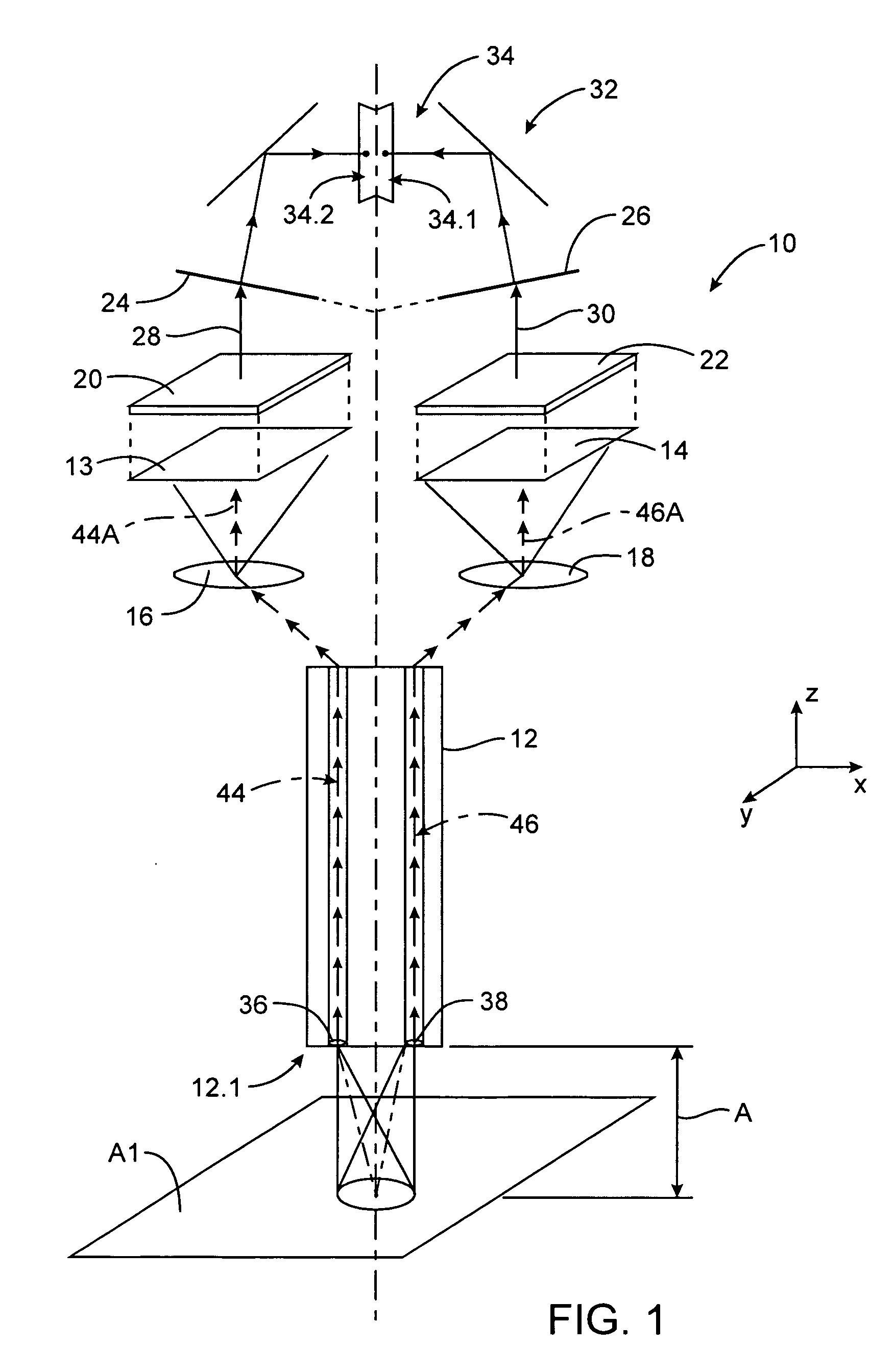
[0035]Referring to the drawings, and with specific reference to FIG. 1, an imaging system, in accordance with the invention, is generally indicated by reference numeral 10.

[0036]While the preferred embodiments of the present invention are described as including converting the various optical images into regulatable information in the form of digital information, other forms of regulatable information could also be used, such as, for example, analogue information from a video and a sync signal, as will be apparent to one of ordinary skill in the art upon reading this disclosure.

[0037]Although throughout the rest of this specification the invention will be described with reference to its application in a minimally invasive surgical apparatus employing an image capturing device in the form of an endoscope, it is to be understood that the field of the invention is not necessarily limited to this application. Accordingly, the invention can be used in, e.g., open surgery, also.

[0038]The s...


PUM


Abstract

This invention relates to a stereo imaging system for use in telerobotic systems. A method of imaging a target site in a stereo imaging system is provided. The method typically includes capturing a right and a left optical image of the target site and transforming the right and the left optical images preferably into digital information. The method further includes converting the digital information into opposed images of the target site displayed on a stereo display of the stereo imaging system, one of the opposed images being associated with the right optical image and the other of the opposed images being associated with the left optical image. The method further includes regulating the digital information to cause the positions of the target site displayed on the opposed images to change relative to each other. The invention further provides for a method of aligning the opposed images, to a method of adjusting the stereo working distance of an image capture device, such as an endoscope and to a stereo imaging system.

Description

CROSS REFERENCE TO RELATED APPLICATIONS[0001]This application is a divisional of U.S. Ser. No. 09 / 378,173, filed on Aug. 20, 1999, now U.S. Pat. No. 6,720,988, which claims the benefit of priority from U.S. Ser. No. 60 / 111,714, filed Dec. 8, 1998, the full disclosures of which are incorporated herein by reference.BACKGROUND OF THE INVENTION[0002]This invention relates to stereo imaging systems, devices, and methods. In particular, the invention relates to a method of imaging a target site with a stereo imaging system, a method of aligning images of a stereo imaging system, a method of adjusting the stereo working distance of a stereo imaging system, and a stereo imaging system.[0003]In minimally invasive surgery such as laparoscopic surgery, for example, a patient's abdomen is insufflated with gas, and trocar sleeves or cannulas are passed through small incisions to provide entry ports for laparoscopic surgical instruments. The laparoscopic surgical instruments generally include an ...

Claims


Application Information

Patent Timeline
Patent Type & Authority Patents(United States)
IPC IPC(8): A61B1/04H04N13/00H04N5/225H04N13/239
CPCA61B1/00183A61B1/00193G02B23/2415H04N13/0003H04N13/0246H04N13/0296H04N13/0425H04N13/0239H04N2005/2255H04N13/246H04N13/296H04N13/10H04N13/239H04N13/327H04N23/555
Inventor GERE, DAVIDBURNS, CHRISTOPHER R.STERN, JOHN D.TIERNEY, MICHAEL J.
Owner INTUITIVE SURGICAL OPERATIONS INC
Learn More