Heater for aircraft potable water tank

a technology for aircraft and water tanks, applied in the direction of fluid heaters, heater elements, lighting and heating apparatus, etc., can solve the problem of reducing the labor time of wire winding

Inactive Publication Date: 2007-10-02
THE BF GOODRICH CO
View PDF43 Cites 9 Cited by
  • Summary
  • Abstract
  • Description
  • Claims
  • Application Information

AI Technical Summary

Benefits of technology

[0009]The present invention provides a heater assembly for a potable water tank wherein the heating element will remain electrically isolated regardless of the integrity of the carrier layers. In this manner, the invasion of moisture into the carrier layers will not affect the electrical insulation of the heating element.
[0011]The fiber overwrap serves to protect the electrically insulating coating, whereby the coating can remain intact before, during, and after the manufacture of a heater blanket. Specifically, the overwrap prevents pins on the work platform from nicking or creasing the coating during winding, eliminates “cold-flows” around pin-imposed corners, and guards against fingernail and other handling damage. By keeping the electrically insulating coating intact, the integrity of carrier layers is not crucial to the electrical insulation of the heating element. Additionally (or alternatively), the overwrap provides a surface for the uncured silicone to mechanically grip during the winding process. This significantly decreases wire-winding labor time. For example, a winding process which would have taken about six to seven hours with unwrapped Teflon-coated wire would take about one to two hours with the present invention.
[0013]The wire structure and / or the crimp joint of the present invention are believed to provide adequate electrical insulation independent of other components of the heater. In other words, the wire structure and / or the crimp joint could satisfy electrical insulation requirements without having to be embedded or encapsulated further in an insulating medium. This greatly increases the ability of the heater to meet some rigorous requirements that conventional heaters could not even hope to satisfy. For example, a heater can be constructed according to the present invention that meets dielectric and insulation requirements during and after withstanding total immersion in a saltwater solution (i.e., waterproof) while undergoing seven vacuum cycles per day (to simulate altitude cycling of the aircraft) for a total duration of thirty days.

Problems solved by technology

This significantly decreases wire-winding labor time.

Method used


Image

  • Heater for aircraft potable water tank
  • Heater for aircraft potable water tank
  • Heater for aircraft potable water tank

Examples


Embodiment Construction

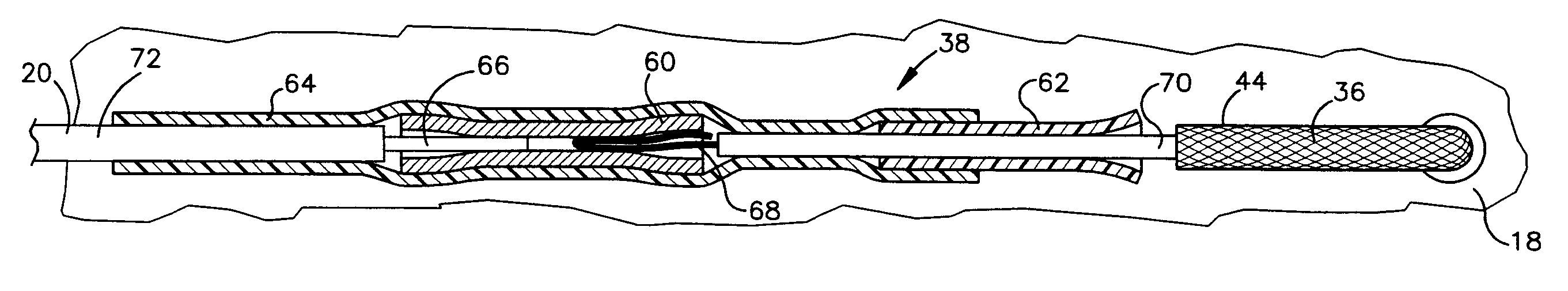
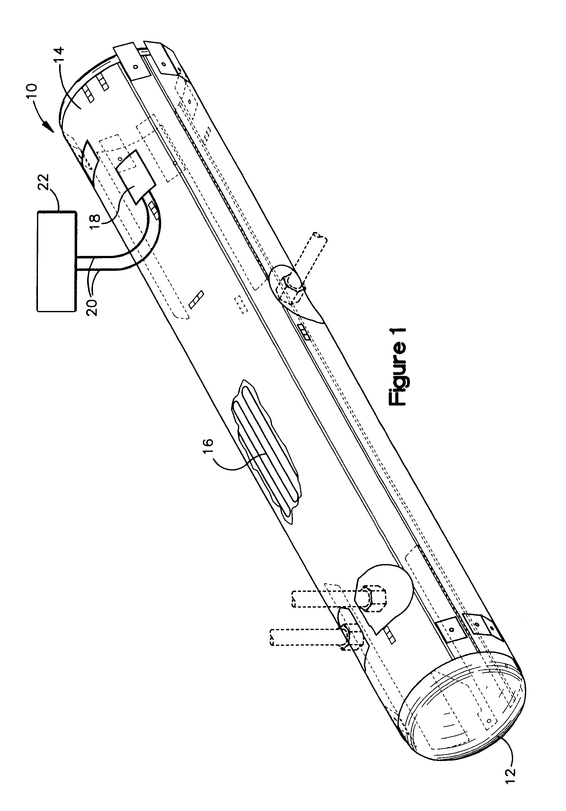
[0027]Referring now to the drawings, and initially to FIG. 1, a heater 10 according to the present invention is shown installed on a potable water tank 12. The heater 10 comprises a blanket 14 including an electrical resistance heating element 16 and a connection pad 18 for electrically connecting the heating element 16 to lead lines 20 to an aircraft power source 22. The water tank 12 is typically positioned under the cabin floor or other locations on an aircraft which are susceptible to cold temperatures, moisture invasion, and pressure drops / rises caused by changing altitudes. The heater 10 maintains the tank 12 at an acceptable temperature range and prevents freezing of the water.

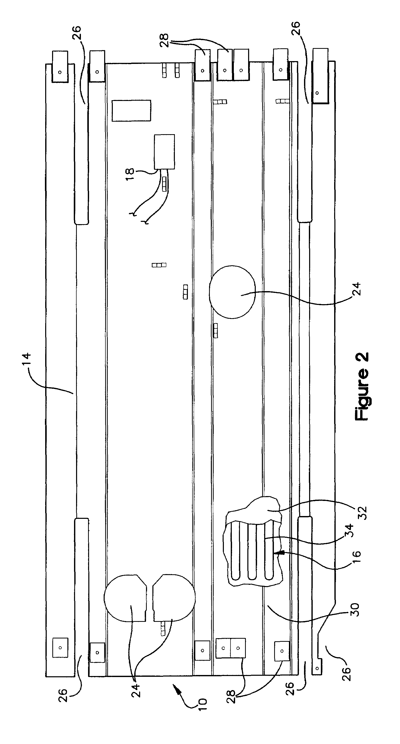
[0028]Referring now to FIG. 2, the heater 10 is shown isolated from the water tank. The blanket 14 is shaped and sized to correspond to the geometry of the water tank 12 (FIG. 1) whereby, in the illustrated embodiment, it has a roughly rectangular shape corresponding to the tank's cylindrical geometry. ...


PUM


Abstract

A heater (10) for installation on a potable water tank (12). The heater (10) comprises a blanket (14) including an electrical resistance heating element (16) and a connection pad (18) for electrically connecting the heating element (16) to lead lines (20) to an aircraft power source (22). The water tank (12) is typically positioned under the cabin floor or other locations on an aircraft which are susceptible to cold temperatures, moisture invasion, and pressure drops / rises caused by changing altitudes. The heater (10) maintains the tank (12) at an acceptable temperature range and prevents freezing of the water.

Description

RELATED APPLICATION[0001]This application claims priority under 35 U.S.C. §120 to U.S. patent application Ser. No. 10 / 434,649 filed on May 9, 2003 which claimed priority under 35 U.S.C. § 119(e) to U.S. Provisional Patent Application No. 60 / 379,721 filed on May 10, 2002. The entire disclosures of these earlier applications are hereby incorporated by reference.FIELD OF THE INVENTION[0002]The present invention relates generally as indicated to a heater for an aircraft potable water tank and, more particularly, to a heater comprising a blanket with an electrical resistance heater element.BACKGROUND OF THE INVENTION[0003]An aircraft typically has one or more potable water tanks on board to accommodate the aircraft's plumbing system. Such water tanks are commonly cylindrical in shape and can range in size depending upon the aircraft and / or the number of tanks on board. In any event, a potable water tank is typically positioned under the cabin floor or other locations on the aircraft whic...

Claims


Application Information

Patent Timeline
Patent Type & Authority Patents(United States)
IPC IPC(8): F24H1/18H01C1/08H01C3/00H01C3/06H01C3/20H05B3/36H05B3/46H05B3/58
CPCH01C1/08H01C3/00H01C3/06H01C3/20H05B3/36H05B3/56H05B3/565H05B3/46H05B2203/021H05B2203/003H05B2203/017
Inventor GIAMATI, MICHAEL J.
Owner THE BF GOODRICH CO
Why Eureka
Try Eureka