
Radio frequency identification tag based speedometer calibration

a radio frequency identification and speedometer technology, applied in the field of data processing system, can solve the problems of driver inadvertently violating the law or other driving parameters, odometer calibration still exits, and the difference between the perceived speed and distance measured by the vehicle and the actual speed and distance of the vehicle,

Inactive Publication Date: 2007-10-02
IBM CORP
View PDF10 Cites 46 Cited by
  • Summary
  • Abstract
  • Description
  • Claims
  • Application Information

AI Technical Summary

Problems solved by technology

With all of this emerging technology, however, a problem still exits with speedometer and odometer calibration.
For example, tires that are oversized, undersized, over-inflated, under-inflated, worn out, or otherwise changed may cause differences between the perceived speed and distance as measured by the vehicle and the actual speed and distance of the vehicle.
Incorrect speed measurements may cause a driver to inadvertently violate the law or other driving parameters.
An incorrect odometer may lead to inaccurate information or driver confusion.

Method used


Image

  • Radio frequency identification tag based speedometer calibration
  • Radio frequency identification tag based speedometer calibration
  • Radio frequency identification tag based speedometer calibration

Examples


Embodiment Construction

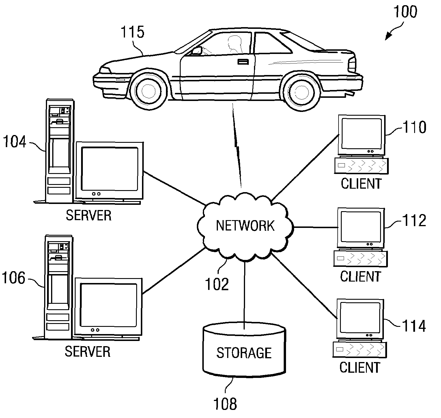
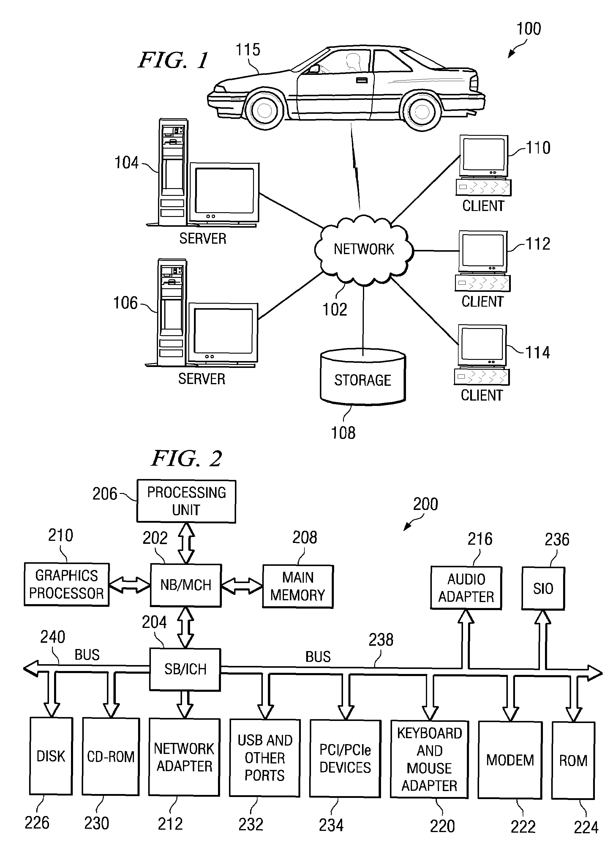
[0016]With reference now to the figures and in particular with reference to FIGS. 1-2, exemplary diagrams of data processing environments are provided in which illustrative embodiments may be implemented. It should be appreciated that FIGS. 1-2 are only exemplary and are not intended to assert or imply any limitation with regard to the environments in which different embodiments may be implemented. Many modifications to the depicted environments may be made.

[0017]With reference now to the figures, FIG. 1 depicts a pictorial representation of a network of data processing systems in which illustrative embodiments may be implemented. Network data processing system 100 is a network of computers in which embodiments may be implemented. Network data processing system 100 contains network 102, which is the medium used to provide communications links between various devices and computers connected together within network data processing system 100. Network 102 may include connections, such ...


PUM


Abstract

A computer implemented method, apparatus, and computer usable program code for calibrating a speedometer of a vehicle. First information is received by the vehicle from a first radio frequency identification tag. Second information is received by the vehicle from a second radio frequency identification tag. A first measured speed of the vehicle is determined based on a reading from the speedometer and a second measured speed of the vehicle is determined using an elapsed time between when the first information was read and when the second information was read and a predetermined distance. The speedometer is calibrated based on a speed difference between the first measured speed and the second measured speed.

Description

BACKGROUND OF THE INVENTION[0001]1. Field of the Invention[0002]The present invention relates generally to an improved data processing system and in particular, to a data processing system located within a vehicle. Still more particularly, the present invention relates to a computer implemented method and apparatus for calibrating a vehicle speedometer.[0003]2. Description of the Related Art[0004]The use of computers has become more and more pervasive in society. This pervasiveness includes the integration of personal computers into vehicles. The utilization of computer technology is employed to provide users or drivers with a familiar environment. In this manner, a user's ability to easily use computing resources in an automobile is provided. In addition, it is envisioned that car buyers would be able to use most of the same software elements in an automobile that are used at home or in the office. Further, an automobile owner could completely customize driver information displays ...

Claims


Application Information

Patent Timeline
IPC IPC(8): G08G1/00
CPCG01P21/02G01P3/66
Inventor DEWITT, JR., JIMMIE EARLHUSSAIN, RIAZ Y.LEVINE, FRANK ELIOTPINEDA, ENIO MANUEL
Owner IBM CORP
Learn More