Machine for filling containers

a filling machine and container technology, applied in the direction of transportation and packaging, liquid handling, packaging goods types, etc., can solve the problems of not being able to move manually by an operator, slow, and sliding the supporting disk vertically, and achieve the effect of cheap and easy production

Inactive Publication Date: 2007-10-09
AZIONARIA CONSTR MASCH AUTOMATICHE A C M A SPA
View PDF11 Cites 25 Cited by
  • Summary
  • Abstract
  • Description
  • Claims
  • Application Information

AI Technical Summary

Benefits of technology

[0006]It is an object of the present invention to provide a machine for filling containers, designed to eliminate the aforementioned drawbacks, and which, in particular, is cheap and easy to produce.

Problems solved by technology

Sliding the supporting disk vertically with respect to the conveyor, however, is a slow, complicated job, in that the supporting disk is relatively heavy, and therefore cannot be moved manually by an operator, and, what is more, is connected to the tank and all the conduits supplying the product with which the bottles are filled.
In actual use, however, the centrifugal force generated by rotation of the conveyor on the bottle hanging by its neck tends to tilt and oscillate the hanging bottle with respect to the vertical, thus resulting in a random error in the bottle weight measured by a load cell interposed between the gripper and conveyor.

Method used


Image

  • Machine for filling containers
  • Machine for filling containers
  • Machine for filling containers

Examples


Embodiment Construction

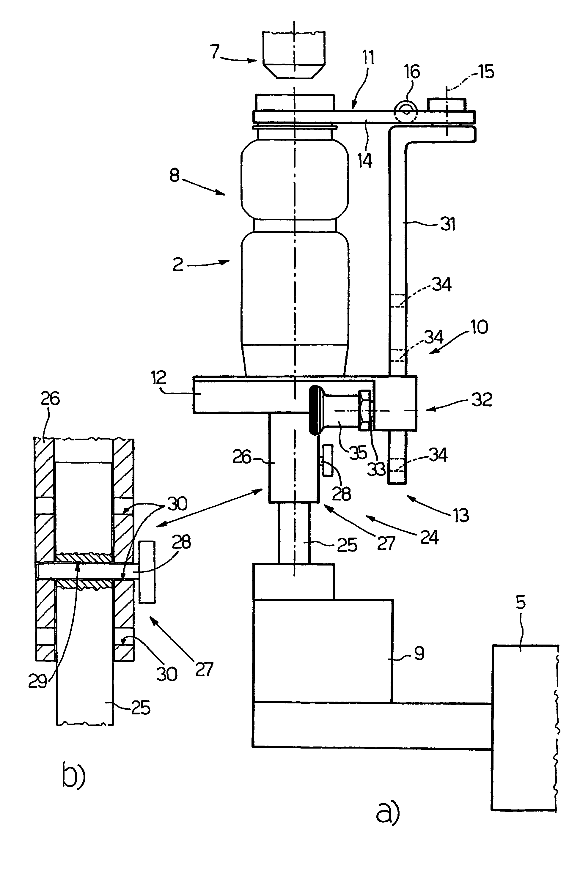
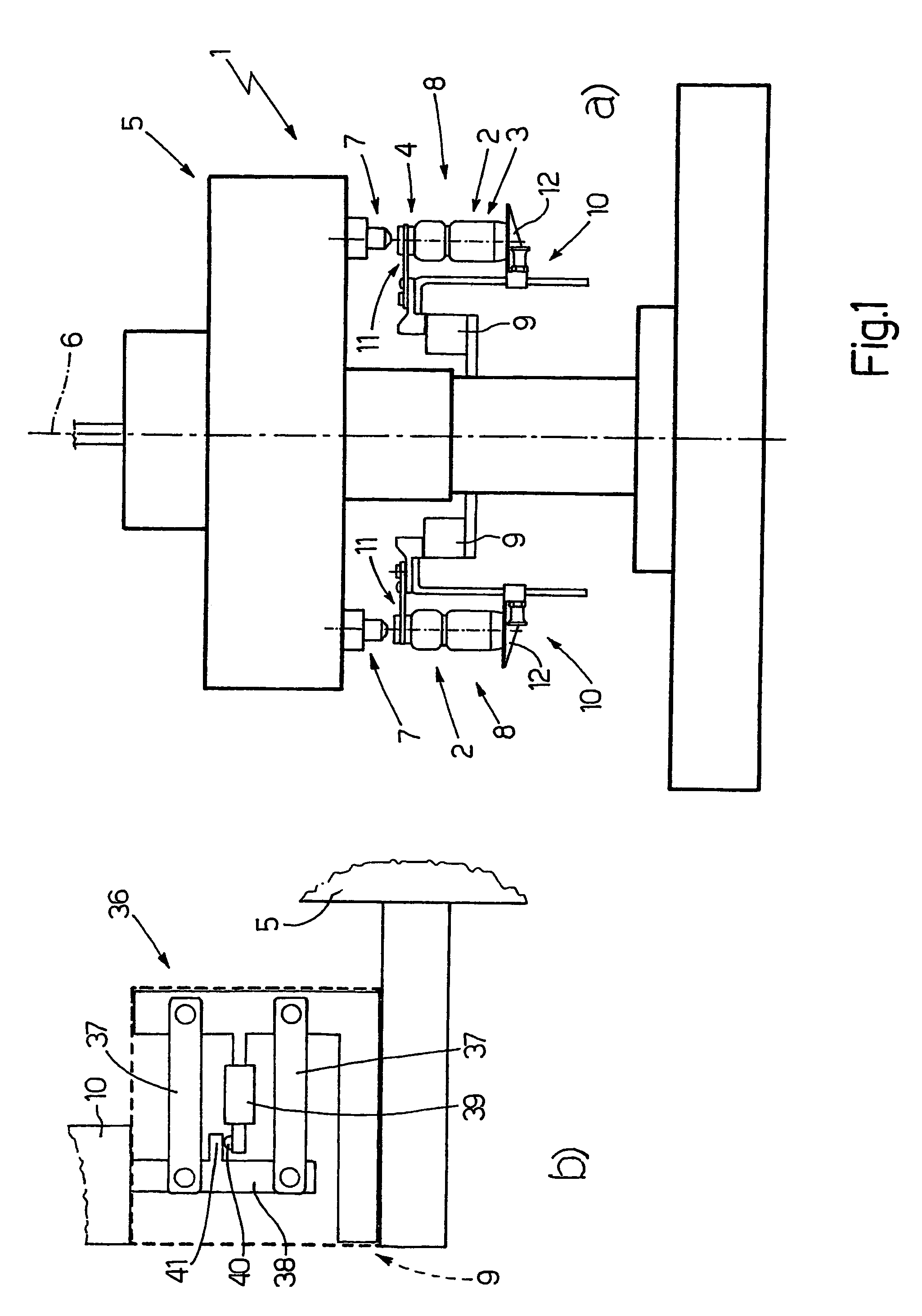
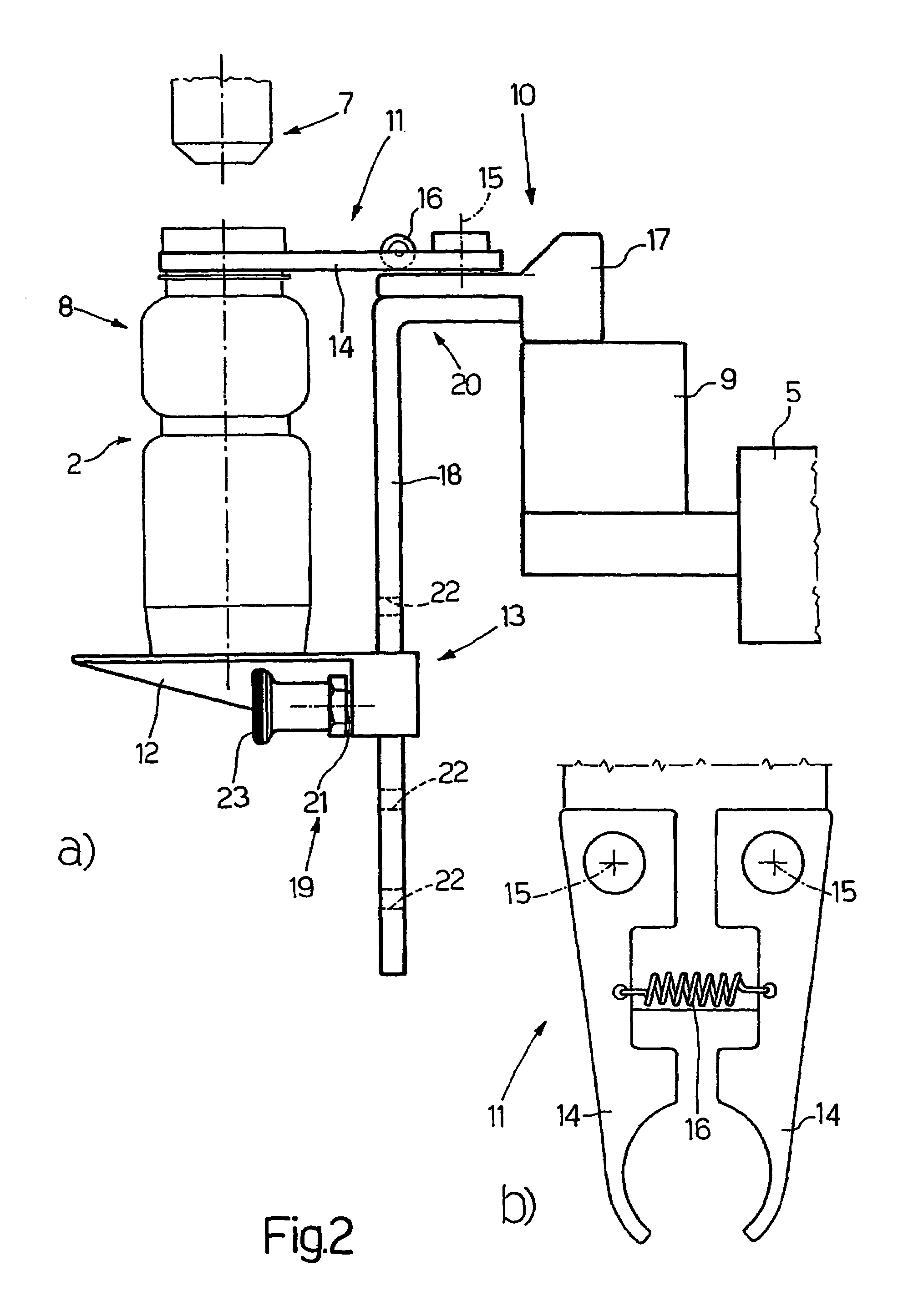
[0012]Number 1 in FIG. 1 indicates as a whole a filling machine for filling bottles 2, each of which comprises a substantially cylindrical body 3, which tapers at the top to form a neck 4 having a threaded end portion for closure by a threaded cap (not shown). Filling machine 1 comprises a carousel conveyor 5 having a vertical axis 6, and in turn comprising a number of filling heads 7, and an equal number of seats 8, each of which houses a respective bottle 2, is associated with a respective filling head 7, and is connected to conveyor 5 via the interposition of a weighing device 9 fitted to conveyor 5 in a fixed position. Weighing device 9 provides for real-time weighing bottle 2 as it is being filled; and the real-time weight measurement of bottle 2 is used to feedback control relative filling head 7 and to ensure bottle 2 is filled with exactly the desired amount of product.

[0013]In actual use, an empty bottle 2 is fed into a respective seat 8 at a known input station (not shown)...


PUM

PropertyMeasurementUnit
weightaaaaaaaaaa
sizeaaaaaaaaaa
heightaaaaaaaaaa

Abstract

A machine (1) for filling containers (2) has a carousel conveyor (5) having a vertical axis (6) and in turn having a number of filling heads (7), and an equal number of seats (8), each of which houses a respective container (2), is associated with a respective filling head (7), and is connected to the carousel conveyor (5) via the interposition of a weighing device (9) supported in a fixed position by the carousel conveyor (5). Each seat (8) has a frame (10), which supports a gripper (11) for engaging a top portion (4) of a respective container (2), and a plate (12) defining a horizontal supporting surface for the bottom of the respective container (2), and an adjusting device (13) for adjusting the vertical position of the plate (12), while maintaining the gripper (11) in a given vertical position close to the respective filling head (7).

Description

TECHNICAL FIELD[0001]The present invention relates to a machine for filling containers.[0002]The present invention may be used to particular advantage for filling bottles, to which the following description refers purely by way of example.BACKGROUND ART[0003]Known bottle-filling machines, such as the type described in Patent IT-1136276, comprise a vertical-axis carousel conveyor having a number of seats, which are arranged symmetrically about the vertical axis of the conveyor, house respective bottles by means of a horizontal supporting surface, and are connected to the conveyor in fixed positions. Each seat is associated with a filling head, which is fitted to a supporting disk connected to the conveyor so as to slide with respect to and along the vertical axis of the conveyor, and fills a bottle housed in the respective seat as the conveyor rotates. A load cell is interposed between each seat and the conveyor to real-time weigh the bottle as it is being filled. The real-time bottl...

Claims


Application Information

Patent Timeline
Patent Type & Authority Patents(United States)
IPC IPC(8): B65B1/30B67C3/20B67C3/24
CPCB67C3/242B67C3/202
Inventor CAVALLARI, STEFANO
Owner AZIONARIA CONSTR MASCH AUTOMATICHE A C M A SPA
Why Eureka
Try Eureka