Method and apparatus for automatic network address assignment

a network address and automatic technology, applied in the field of network appliances, can solve the problems of manual labor in the installation process of network appliances, loss of network configuration of network appliances,

Inactive Publication Date: 2007-10-09
CISCO TECH INC
View PDF2 Cites 72 Cited by
  • Summary
  • Abstract
  • Description
  • Claims
  • Application Information

AI Technical Summary

Benefits of technology

[0015]The appliance may also determine a subnet mask for the subnet to which it is coupled. To isolate the subnet mask, the appliance searches potential subnet masks, in a binary search manner in one embodiment, to determine the boundary defined by the subnet mask; other typical search techniques applicable to isolating potential subnet masks may be used rather than a binary search. The boundary is located in-between ones and zeros when the subnet mask is represented as a binary number. To ensure the unused network address is not in use by another network or subnet device, the appliance performs a final check of that potentially unused IP address. In the event an IP conflict occurs during the final check, the appliance provides a means for correcting the IP conflict.

Problems solved by technology

One of the major costs of owning and operating network products / appliances is, on an ongoing basis, having someone trustworthy and knowledgeable to keep the configuration of the network appliances such that reconfiguration may be done in the event of a system crash, network appliance failure, or other such event to cause a network appliance to lose its network configuration.
Further, in networks / subnets not having a local server operating as a DHCP (dynamic host configuration protocol) server or boot server, then the process of installing a network appliance becomes a manually intensive task.
It is possible that the above process may have caused an IP conflict, which may cause subnet devices to change their internal routing tables to indicate that the appliance is the router.

Method used


Image

  • Method and apparatus for automatic network address assignment
  • Method and apparatus for automatic network address assignment
  • Method and apparatus for automatic network address assignment

Examples


Embodiment Construction

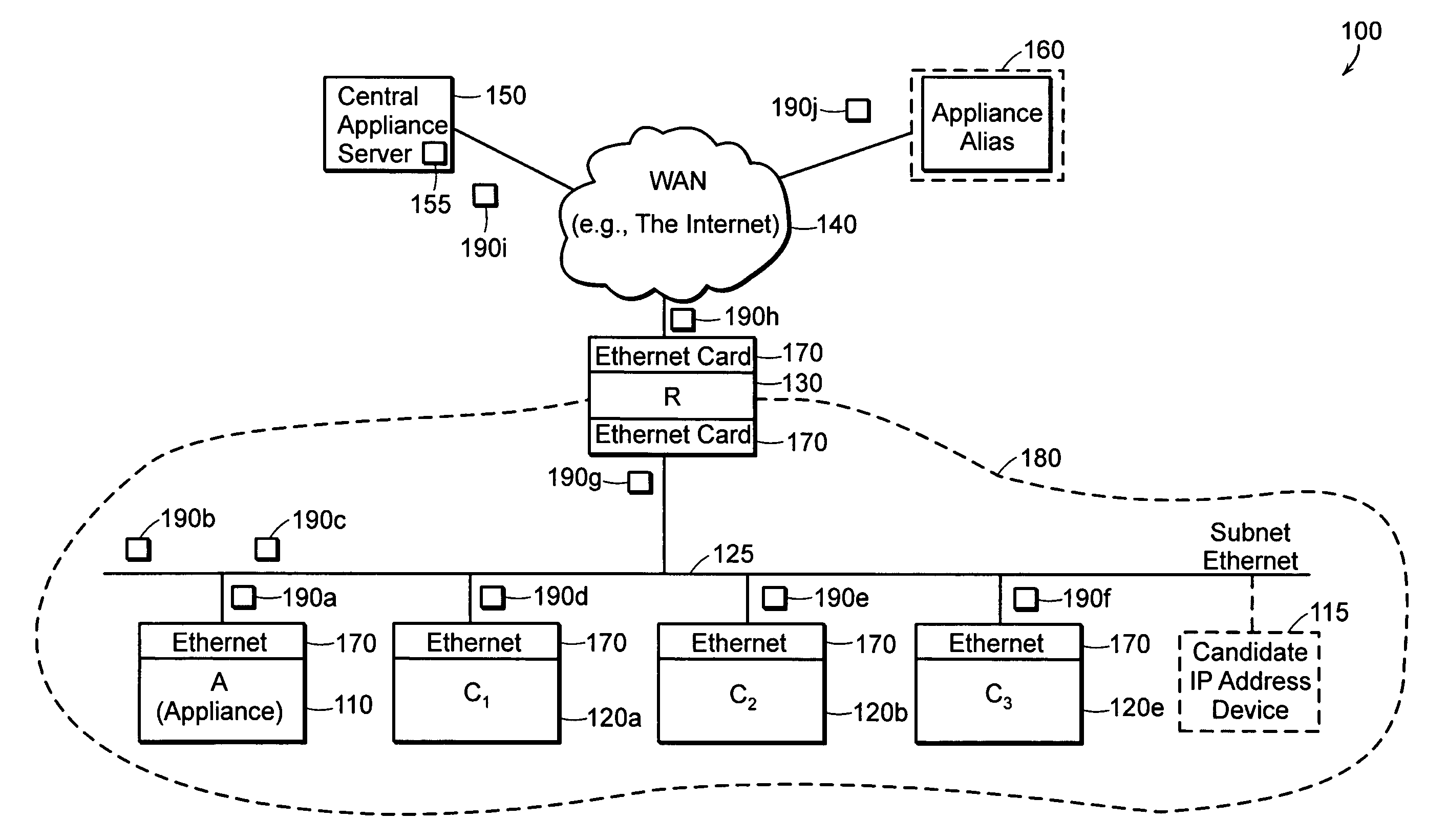
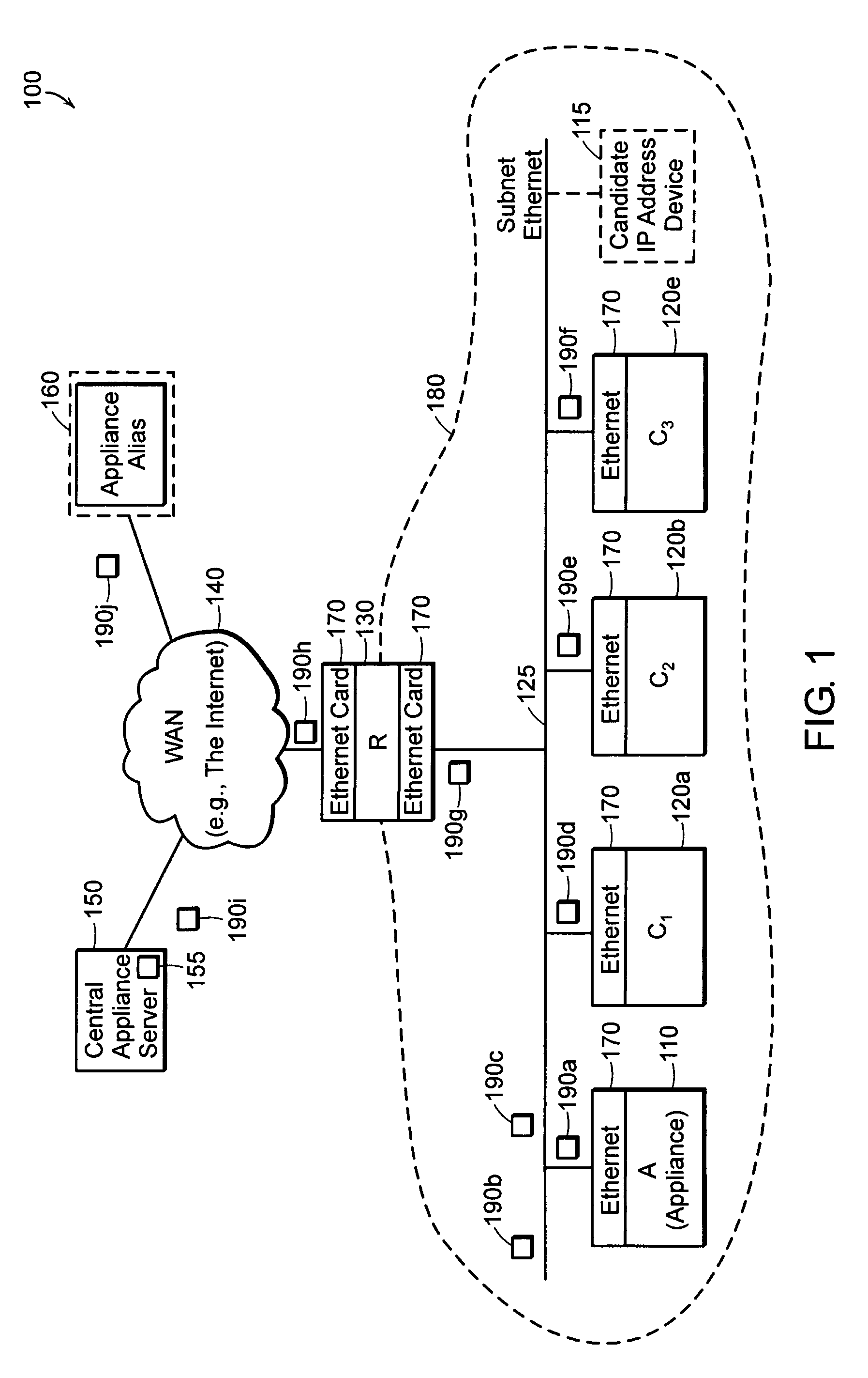
[0038]FIG. 1 is an example of a network 100 in which the present invention is deployed. The network 100 includes a network (WAN) 140 (e.g., the Internet), central appliance server (CAS) 150, appliance alias 160, router 130, and subnet 180. The subnet 180 couples to and communicates with the WAN 140 through the router 130.

[0039]The subnet 180 includes an ethernet 125. Coupled to the ethernet are three computers, C1 120a, C2 120b, and C3 120c. Also coupled to the subnet ethernet 125 is an appliance (A) 110 and router 130. Every electronic device 110, 120, 130 coupled to the ethernet 125 includes an ethernet card 170. For simplicity, the ethernet cards are all depicted as being the same type. Note that the router (R) 130 has two ethernet cards 170—one coupled to the ethernet 125 in the subnet 180 and the other coupled to the WAN 140.

[0040]The devices 110, 120, 130 found at various locations around the network 100 may be referred to as network nodes. Other forms of network nodes include...


PUM


Abstract

The present invention includes a method and apparatus for automatically assigning a network address to a network device in an electronic communications network carrying inter-device communication packets to and from electronic devices located at assigned network addresses. The network device, also referred to as an appliance, communicates with at least one other network device to collect information from inter-device communication packets, which contain network address assignment information. From the network address assignment information in the communication packets, the appliance determines an available network address. The appliance assumes the available network address. The appliance may access a remote network device to retrieve an available, permanent, network configuration, including IP address.

Description

RELATED APPLICATIONS[0001]This application is a Continuation-in-Part of application Ser. No. 09 / 294,836 filed Apr. 19, 1999 now U.S. Pat. No. 6,345,294, granted Feb. 5, 2002. This application claims priority to U.S. Provisional Application No. 60 / 160,535 filed Oct. 20, 1999 entitled “Automatic Network Address Assignment and Translation Inference” (now expired) and U.S. Provisional Application No. 60 / 178,063 filed Jan. 24, 2000 entitled “Method and Apparatus for Automatic Network Address Assignment” (now expired). The contents of the above applications are incorporated herein by reference in their entirety.BACKGROUND OF THE INVENTION[0002]A typical networking appliance product, such as a computer or personal communication unit, which might or might not have a keyboard or monitor and which might not yet have configured except for some factory standard material incorporated into it, must boot when installed into a local area network (LAN). Then, a person near that appliance can configu...

Claims


Application Information

Patent Timeline
Patent Type & Authority Patents(United States)
IPC IPC(8): G06F13/00
CPCH04L29/12028H04L29/1232H04L29/12801H04L29/12933H04L61/6068H04L41/0853H04L61/103H04L61/2092H04L61/6004H04L41/0806H04L61/5092H04L2101/604H04L2101/668
Inventor LU, GANGO'TOOLE, JAMESKAASHOEK, M. FRANS
Owner CISCO TECH INC
Why Eureka
Try Eureka